
Thrust Blocks: The Complete 2026 Engineering Guide for Pipeline Stability
Thrust Blocks are critical specialized structures designed to counteract the internal hydraulic forces within a pressurized pipeline system. These massive concrete structures transfer the resultant force from pipe fittings—such as bends, tees, and valves—safely into the surrounding soil. Without properly engineered Thrust Blocks, the momentum of water or industrial fluids at change-of-direction points can cause joint separation, structural leakage, or catastrophic pipeline failure in both municipal and industrial infrastructure.
What is a Thrust Block?
A thrust block is a mass of concrete cast-in-place between a pipe fitting and the undisturbed soil of a trench wall. Its primary function is to provide a bearing surface that distributes hydraulic thrust over a large enough soil area to prevent pipe movement.
Quick Navigation
Pipeline Engineering Quiz
Question 1 of 51. What is the primary variable used to determine the resultant thrust force at a pipe bend?
Complete Course on
Piping Engineering
Check Now
Key Features
- 125+ Hours Content
- 500+ Recorded Lectures
- 20+ Years Exp.
- Lifetime Access
Coverage
- Codes & Standards
- Layouts & Design
- Material Eng.
- Stress Analysis

What are Thrust Blocks and Anchor Blocks?
In modern 2026 pipeline engineering, distinguishing between Thrust Blocks and Anchor Blocks is vital for structural integrity. While both provide stability, they serve distinct mechanical purposes in managing hydraulic and environmental stresses.
🛡️ Thrust Blocks
Thrust blocks are essential components used to counteract forces generated by fluid movement, especially when direction changes. These thrust forces can cause misalignments if not properly managed.
- Purpose: Absorb and transfer forces to surrounding soil at bends, tees, or elbows.
- Design: Concrete mass strategically positioned against the pipe and undisturbed trench walls.
- Function: Prevents pipes from shifting due to internal pressure at specific fittings.
⚓ Anchor Blocks
Anchor blocks hold a section of pipe in a fixed, absolute position. They prevent any movement caused by internal pressure, thermal expansion, or external forces like soil shifting.
- Purpose: Restrict movement in long straight runs or exposed sections.
- Design: Larger concrete structures providing support at specific intervals or critical points.
- Function: Resists both axial and lateral forces to “anchor” the pipe permanently.
Comparison Table: Thrust Block vs. Anchor Block
| Aspect | Thrust Block | Anchor Block |
|---|---|---|
| Primary Purpose | Absorbs/Distributes forces at fittings. | Secures pipe in a fixed position. |
| Typical Location | Bends, tees, and direction changes. | Along length or at strategic points. |
| Forces Handled | Directional thrust from fluid flow. | Axial forces, thermal expansion. |
| Alignment Role | Ensures alignment at specific fittings. | Keeps the entire pipeline aligned. |
Calculating Block Requirements (2026 Standards)
Thrust Block Formula
F = P × A
P: Internal Pressure (psi or Pa)
A: Cross-sectional Area
Anchor Block Formula
F = σ × A
σ: Stress from pressure, temp, or external loads
A: Area of application
Pipeline Stability Significance
The importance of these structures extends beyond simple support. Properly designed Thrust Blocks reduce stress on fittings, minimizing leaks. Meanwhile, Anchor Blocks enhance durability by neutralizing the effects of thermal expansion—a critical factor in the 2026 design of long-distance oil and gas pipelines and municipal water networks.

Key Components of a Thrust Block and Their Roles
A high-performance thrust block is more than just a mass of concrete. In 2026, engineering specifications for Thrust Blocks require a multi-layered approach to material science and structural design to ensure decades of service life under high-pressure conditions.
Concrete Matrix
Concrete is the primary structural mass. Modern 2026 concrete thrust block standards often specify 4,000 PSI mixes with reduced curing times via specialized additives. Proper moisture retention during the curing process is critical to reaching the optimal compressive strength needed to resist hydraulic surge.
Steel Reinforcement
While concrete handles compression, Steel Rebar is embedded to manage tensile and shear stresses. For large-diameter fittings, a cage-like rebar structure prevents the block from cracking under the bending moments exerted by the pipe.
Interface Protection
To prevent pipe abrasion, rubber or neoprene pads are placed between the fitting and the concrete. This layer cushions the pipe against vibrations and minor thermal movements, reducing localized stress concentrations that could lead to pinhole leaks.
Formwork Design
Precision molds ensure the block achieves the calculated bearing area (Ab). The formwork must be rigid enough to withstand the weight of the wet concrete while ensuring the bearing face is cast directly against the undisturbed virgin soil of the trench.
Protective Coatings
In corrosive or high-water-table environments, waterproofing agents are applied to the block surface. This prevents water ingress and protects the internal steel reinforcement from oxidation and “concrete rot.”
Expansion Joints
For massive Thrust Blocks, compressible fiberboard or rubber joints are used to allow for thermal expansion and contraction. This prevents the block from cracking itself or the pipe during extreme seasonal temperature shifts.
Engineering Insight: A failure in any one of these components—such as omitting the interface pad or using poor-quality soil for the bearing face—can lead to thrust block failure causes like settlement or pipe puncture, regardless of how much concrete is used.
EPCLand YouTube Channel
2,500+ Videos • Daily Updates

Figure 1: Pouring reinforced concrete for a critical pipeline junction in a 2026 infrastructure project.
Technical Theory: The Physics of Hydraulic Thrust
In any pressurized piping system, the fluid exerts force against the walls of the pipe. While these forces are balanced in a straight run of pipe, they become unbalanced at any point where the direction or cross-sectional area changes. This unbalanced force is known as hydrostatic thrust. For engineers, understanding Thrust Block Design for Pipelines is paramount to ensuring that these forces do not lead to joint separation.
The magnitude of this force is a function of the internal pressure, the pipe’s cross-sectional area, and the geometry of the fitting. When water flows through a bend, it creates a resultant force that acts outward, away from the center of the bend. If this force exceeds the friction and mechanical strength of the pipe joints, the pipeline will fail. This is why Thrust Blocks are strategically placed to transfer that energy into the trench wall.
Static vs. Dynamic Forces
While static pressure (working pressure) is the primary driver, engineers must also account for surge pressures, often called “Water Hammer.” Modern 2026 concrete thrust block standards require that the block be designed for the maximum possible surge pressure, which can be 1.5 to 2 times the normal operating pressure. This ensures a safety factor that prevents thrust block failure causes like cracking or soil yielding during pump startups or sudden valve closures.
Sizing & Pipe Bend Thrust Force Calculation
To perform a precise pipe bend thrust force calculation, we must determine the resultant force (T) acting on the fitting. The standard formula used in civil engineering for a horizontal bend is:
T = 2 * P * A * sin(θ / 2)
T = Resultant Thrust Force (lbs or N)
P = Internal Pressure (psi or Pa)
A = Cross-sectional Area of Pipe (sq. in or sq. m)
θ = Angle of the Bend (degrees)
Once the force T is calculated, the thrust block sizing calculation begins. The required bearing area (Ab) of the block against the soil is determined by dividing the thrust force by the safe soil bearing capacity (Sb) and applying a safety factor (typically 1.5).
Required Bearing Area Formula:
Ab = (T * SF) / Sb
Where SF is the Safety Factor and Sb is the Soil Bearing Capacity.
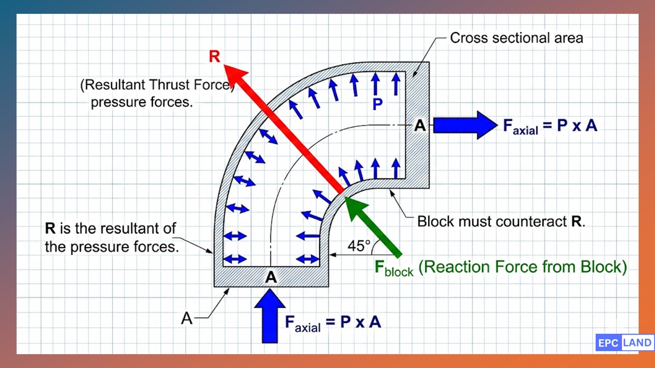
Figure 2: Vector analysis of forces at a 90-degree bend showing resultant thrust direction.
Soil Bearing Capacities & Standards
Adhering to AWWA M11 thrust block guidelines is essential for municipal water projects. The following table provides the estimated safe bearing loads for various soil types, which is the “Sb” variable in our sizing equation.
| Soil Description | Safe Bearing Load (psf) | Engineering Class |
|---|---|---|
| Muck, Peat, Soft Clay | 0 – 500 | Unsuitable |
| Sand and Gravel (Saturated) | 1,000 – 1,500 | Medium Risk |
| Sand and Gravel (Dry/Compacted) | 2,000 – 3,000 | Ideal |
| Hard Pan / Shale | 5,000 – 10,000 | High Strength |
Restrained Joint vs Thrust Block
In modern engineering, the choice between a restrained joint vs thrust block often depends on site constraints. While Thrust Blocks are cost-effective for new installations in open fields, restrained joints are preferred in congested urban corridors where there is no room to pour large concrete masses.
- Thrust Blocks: Rely on soil bearing capacity. Simple to design but require large excavations.
- Restrained Joints: Use mechanical bolts or welds to transfer force along the pipe length via friction between the pipe and soil. No concrete curing time required.
For critical high-pressure lines, engineers often use a hybrid approach: reinforcing Thrust Blocks with steel rebar to increase their internal shear strength, especially when dealing with large diameter (over 24-inch) steel or ductile iron pipes.
Case Study: Failure Analysis of Thrust Blocks in Saturated Soils
Location
Coastal Municipal District, 2026 Project
Equipment
24″ Ductile Iron Pipe (DI) @ 150 PSI
Primary Concern
45-Degree Horizontal Bend Displacement

Figure 3: Forensic excavation showing the separation of the 45-degree fitting from the primary concrete block after soil liquefaction.
The Failure Incident
In early 2026, a major water main servicing a coastal municipality experienced a significant pressure drop and subsequent ground subsidence near a critical 45-degree bend. Upon excavation, the engineering team discovered that the fitting had moved approximately 6 inches away from its original alignment. The Thrust Blocks designed to hold the fitting in place remained largely intact but had rotated and sunk into the sub-grade.
Root Cause: Unexpected Soil Liquefaction
A forensic geotechnical investigation revealed that a localized rise in the water table, combined with minor seismic vibrations from nearby heavy rail transit, triggered a “liquefaction-like” state in the sandy-silt trench bedding. This is one of the most overlooked thrust block failure causes.
When the soil became saturated, the Sb (Soil Bearing Capacity) used in the initial Thrust Blocks design dropped from a calculated 2,500 psf to nearly 400 psf. The hydraulic thrust force at the 45-degree bend, calculated at approximately 28,000 lbs, easily overcame the diminished resistance of the softened soil. The block, while massive enough in concrete volume, did not have sufficient bearing area (Ab) to stabilize the pipeline under these extreme environmental conditions.
Forensic Force Breakdown:
- Operating Pressure (P): 150 psi
- Bend Angle (θ): 45 degrees
- Original Soil Capacity (Sb): 2,500 psf (Dry)
- Failure Soil Capacity (Sb): 400 psf (Saturated)
- Required Bearing Area at Failure: 70 sq. ft (The original design provided only 14 sq. ft)
The Solution & 2026 ROI Analysis
Rather than simply pouring more concrete, the engineering team implemented a multi-stage remediation plan:
- Soil Stabilization: High-pressure grout injection was used to solidify the surrounding sandy-silt matrix, restoring the Sb to 3,000+ psf.
- Hybrid Restraint: The damaged 45-degree fitting was replaced with a new DI fitting and secured using restrained joints in addition to a newly cast-in-place thrust block.
- Gravity Augmentation: The new Thrust Blocks were designed with a larger footprint and deeper vertical profile to leverage the weight of the backfill (overburden) as additional resistance.
The result: The system was restored to full service within 72 hours. While the initial repair cost was 15% higher than a standard block replacement, the 2026 ROI is projected to be significant, as the hybrid design prevents future failures during inevitable seasonal water table fluctuations.
Frequently Asked Questions
How do I perform a precise thrust block sizing calculation?
What are the current 2026 concrete thrust block standards?
How do AWWA M11 thrust block guidelines differ from other codes?
What are the most common thrust block failure causes in 2026?
Final Engineering Summary
In 2026, the implementation of Thrust Blocks remains a fundamental pillar of pipeline integrity. While the physics of hydraulic thrust has not changed, our methods for analysis have become significantly more sophisticated. By integrating precise pipe bend thrust force calculation with modern geotechnical data and adhering to rigorous concrete thrust block standards, engineers can build resilient infrastructure that withstands both operational surges and environmental shifts.
Whether you choose a traditional concrete mass or a restrained joint vs thrust block hybrid approach, the priority must always be the safety and longevity of the distribution network. Always consult the latest AWWA M11 thrust block guidelines and local geotechnical reports before finalizing any design to ensure long-term stability.

Related posts:
![High-grade industrial Wing Nut Types and Applications for mechanical assemblies.]()
Wing Nut Types and Applications: The 2026 Engineering Guide
![Industrial Monorail Crane Systems installed in a modern manufacturing plant 2026.]()
Monorail Crane Systems: Design, Types & 2026 Standards Guide
![Lead engineer performing a Factory Acceptance Test FAT on an industrial skid system 2026]()
Factory Acceptance Test FAT: The 2026 Engineering Guide to Zero-Defect Delivery
![Professional engineering workspace showing a Basis of Design document layout for a 2026 project.]()
Basis of Design: How to Write a BOD for Engineering Projects in 2026
![Industrial Flare Knockout Drum Sizing and installation in a refinery relief system.]()
Flare Knockout Drum Sizing: Design & API 521 Standards (2026 Guide)
![Advanced Reboiler Control Systems in a modern petrochemical refinery 2026.]()
Reboiler Control Systems: Engineering Guide to Precision Control 2026


