Thrust Block Design and Anchor Block Calculations

Robust Thrust Block Design is the absolute cornerstone of pipeline integrity, ensuring that unbalanced hydraulic forces do not cause catastrophic joint separation or pipe rupture. When fluids change direction or stop within a pressurized piping system, the momentum transfer creates significant “thrust forces” that must be transferred safely into the surrounding soil or structure. Without proper anchoring, even low-pressure lines can shift enough to cause leaks, environmental damage, and costly downtime.
What is a Thrust Block?
A Thrust Block is a mass of concrete (or soil) poured between a pipeline fitting (like a bend, tee, or reducer) and the undisturbed soil. Its primary function is to transfer the resultant hydraulic thrust force from the pipe to the soil, preventing joint separation. Unlike an Anchor Block, which fully restrains the pipe against movement in all directions (often used for thermal expansion control), a thrust block typically resists force in only one specific vector.
⚡ Engineering Knowledge Check
Question 1 of 5
Complete Course on
Piping Engineering
Check Now
Key Features
- 125+ Hours Content
- 500+ Recorded Lectures
- 20+ Years Exp.
- Lifetime Access
Coverage
- Codes & Standards
- Layouts & Design
- Material Eng.
- Stress Analysis
Fundamentals of Thrust Block Design
In pressurized piping systems, forces are balanced as long as the fluid flows in a straight line with a constant diameter. However, whenever the pipeline changes direction (bends), changes size (reducers), or terminates (dead ends), the internal pressure and the momentum of the moving fluid create unbalanced forces. This is where Thrust Block Design becomes critical engineering.
According to standards like ASME B31.1 (Power Piping) and AWWA M11 (Steel Pipe), these forces must be restrained to prevent the joints from separating. While welded steel lines often self-restrain due to the tensile strength of the steel, gasketed systems like Ductile Iron (DI) or PVC rely entirely on external restraint. The total thrust force is a vector combination of:
- Hydrostatic Pressure Force: The internal pressure acting on the projected area of the fitting.
- Momentum Force: The dynamic force caused by the change in fluid velocity (typically negligible in waterworks unless velocities exceed 10 ft/s).
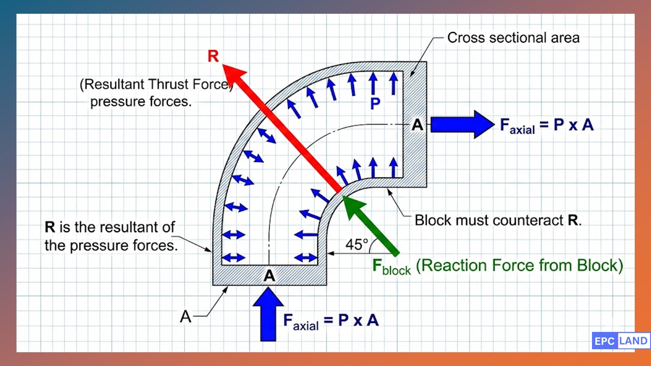
The Thrust Block Calculation Formula
To size a block correctly, engineers must first determine the magnitude of the Resultant Force (R). The thrust block calculation formula for a horizontal bend is derived from simple vector mechanics. It is vital to use the peak pressure anticipated during the system's life—typically the hydrostatic test pressure loads, which are often 1.5 times the operating pressure.
Resultant Force Equation
R = 2 × P × A × sin(θ / 2)
- R = Resultant Thrust Force (lbs or N)
- P = Design Pressure (psi or Pa)
- A = Cross-Sectional Area of Pipe ID (in² or m²)
- θ = Angle of the Bend (degrees)
Sizing the Bearing Area (Ab)
Once R is known, the size of the concrete block is determined by the soil bearing capacity. The block functions by transferring the load R directly into the undisturbed trench wall. The required bearing area (Ab) is calculated as:
Ab = (R × Sf) / Sb
Where Sf is the Safety Factor (typically 1.5) and Sb is the allowable soil bearing pressure. If the soil is too soft (like peat or loose sand), the block size may become impractical, requiring piles or tie-rods.
Typical Soil Bearing Capacities (Sb) for Design
Always verify with a site-specific Geotechnical Report.
| Soil Type | Allowable Bearing (lb/ft²) | Allowable Bearing (kPa) | Notes |
|---|---|---|---|
| Muck / Peat | 0 | 0 | Requires Piles/Removal |
| Soft Clay | 1,000 | 48 | Risk of long-term settlement |
| Sand (Compacted) | 2,000 - 3,000 | 96 - 144 | Must be confined |
| Sand & Gravel | 3,000 - 4,000 | 144 - 192 | Ideal for standard blocks |
| Shale / Hard Rock | 10,000+ | 480+ | Requires minimal concrete |
Restrained Joints vs. Thrust Blocks
In modern urban environments, pouring massive concrete blocks is often impossible due to existing utilities or lack of space. This leads to the "Restrained Joints vs Thrust Blocks" debate.
Thrust Blocks
- Pros: Simple to design, uses cheap materials (concrete), effective in stable virgin soil.
- Cons: Takes up space, requires curing time, risky in seismic zones, hard to modify later.
Restrained Joints
- Pros: No concrete curing, installs fast, works in congested corridors, flexible during earthquakes.
- Cons: Higher material cost (locking gaskets/bolts), relies on pipe-soil friction (requires calculation of "restrained length").
For many high-density polyethylene (HDPE) or welded steel projects, internal restraint is preferred. However, pipeline anchor block details differ from standard thrust blocks. Anchors are designed to grip the pipe 360 degrees to prevent axial movement caused by thermal expansion or vibration, rather than just pushing against the soil on one side.
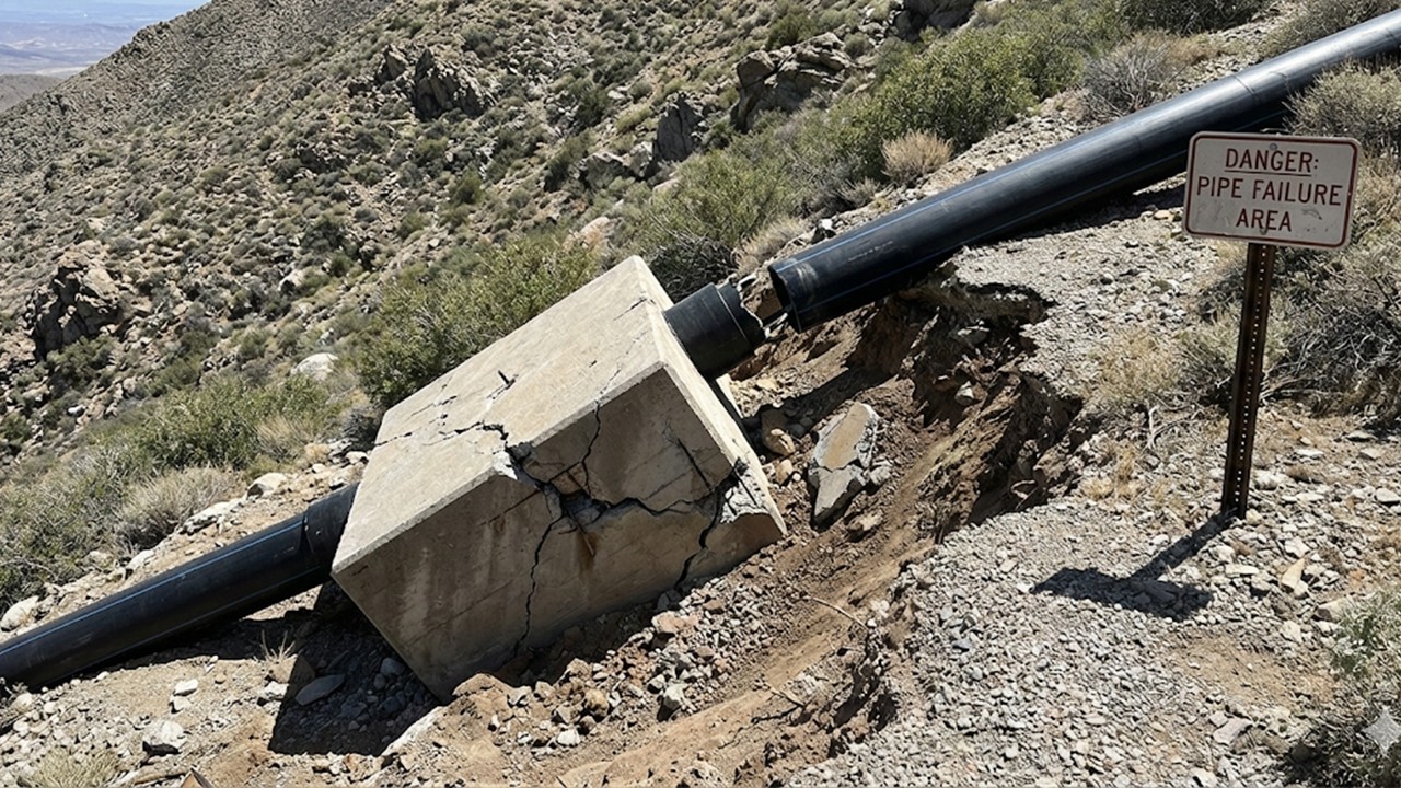
Case Study: Thrust Block Design Failure on Steep Slope Penstock
Project Parameters
The Problem: Misidentifying Forces
The initial design specified a standard gravity Thrust Block at the toe of the slope to counteract the hydrostatic outward thrust caused by the 45-degree vertical bend. The engineering team calculated the force based solely on internal pressure:
R = 2 × 110 psi × 968 in² × sin(22.5°) ≈ 81,000 lbs
However, during the first winter freeze, the pipe physically pulled out of the concrete block, moving 4 inches uphill. The failure was not due to pressure blowout, but due to ignoring HDPE pipe thermal expansion (and contraction).
Root Cause Analysis
Unlike steel or ductile iron, HDPE has a thermal expansion coefficient approx. 15 times higher (~1.2 × 10⁻⁴ in/in/°F). When the temperature dropped by 60°F from the installation temperature, the pipe contracted massively.
The block was designed as a "Thrust Block" (resisting compression against soil) rather than an "Anchor Block" (resisting axial tension). The smooth surface of the HDPE pipe offered minimal friction against the concrete. The thermal retraction force exceeded the shear bond strength, causing the pipe to slip.
The Solution: True Anchor Implementation
The retrofit required converting the passive thrust block into a true rigid Anchor Block. The repair involved:
- Electrofusion Flex Restraints: An electrofusion "puddle flange" (anti-shear ring) was fused onto the pipe OD. This ring mechanically locks into the concrete, transferring axial loads positively rather than relying on friction.
- Rebar Cage Integration: The new concrete pour included a rebar cage tied directly to the puddle flange to distribute the point load.
- Expansion Loops: An omega-style expansion loop was installed 200 feet upstream to absorb future thermal movement, reducing the load on the anchor itself.
Validation Result (2025 Audit)
Following the retrofit, the system withstood a -15°F cold snap with zero axial displacement. The facility avoided an estimated $250,000 in potential flood damage and environmental fines.
EPCLand YouTube Channel
2,500+ Videos • Daily Updates
Frequently Asked Questions on Thrust Restraint
How do I apply the thrust block calculation formula for vertical bends?
For vertical bends, gravity plays a major role. If the bend is "concave up" (pushing down), the thrust block calculation formula is similar to horizontal bends, but you must ensure the soil below has adequate bearing capacity. However, if the bend is "concave down" (pushing up), the block must be heavy enough to counteract the upward thrust vector plus a safety factor (usually 1.5). In this case, you are designing a gravity mass anchor, not just a bearing block.
Should I design for operating pressure or hydrostatic test pressure loads?
You must always design for the highest potential pressure the system will experience. In almost all cases, this is the hydrostatic test pressure loads (typically 1.5x the working pressure) applied during commissioning. Designing only for operating pressure is a common cause of failure during initial testing, as the thrust force increases linearly with pressure.
What are the critical pipeline anchor block details for PVC pipe?
PVC is brittle compared to steel. Critical pipeline anchor block details include placing a protective membrane (like felt or rubber) between the pipe and the concrete to prevent point-loading abrasion. Additionally, because PVC is smooth, you cannot rely on concrete bonding alone; you must use mechanical restraint glands (like Mega-Lugs) embedded within the concrete to transfer the force effectively.
When is it better to use restrained joints vs thrust blocks?
Choose restrained joints vs thrust blocks when you are working in congested utility corridors where there is no space for large concrete masses, or where the soil is "muck" with zero bearing capacity. Restrained joints (self-restraining gaskets) distribute the force along the length of the pipe via friction, making them ideal for urban centers or seismic zones where flexibility is required.
Ensure Pipeline Integrity in 2026
Whether you are calculating the bearing area for a massive 48-inch water main or detailing a small PVC irrigation line, the physics remains the same. A failure to respect Thrust Block Design principles can lead to catastrophic joint separation.
Always cross-reference your calculations with local geotechnical data and standards like AWWA M11 or NFPA 24 before pouring concrete.

Related posts:
![High-grade industrial Wing Nut Types and Applications for mechanical assemblies.]()
Wing Nut Types and Applications: The 2026 Engineering Guide
![Industrial Monorail Crane Systems installed in a modern manufacturing plant 2026.]()
Monorail Crane Systems: Design, Types & 2026 Standards Guide
![Lead engineer performing a Factory Acceptance Test FAT on an industrial skid system 2026]()
Factory Acceptance Test FAT: The 2026 Engineering Guide to Zero-Defect Delivery
![Professional engineering workspace showing a Basis of Design document layout for a 2026 project.]()
Basis of Design: How to Write a BOD for Engineering Projects in 2026
![Industrial Flare Knockout Drum Sizing and installation in a refinery relief system.]()
Flare Knockout Drum Sizing: Design & API 521 Standards (2026 Guide)
![Advanced Reboiler Control Systems in a modern petrochemical refinery 2026.]()
Reboiler Control Systems: Engineering Guide to Precision Control 2026


