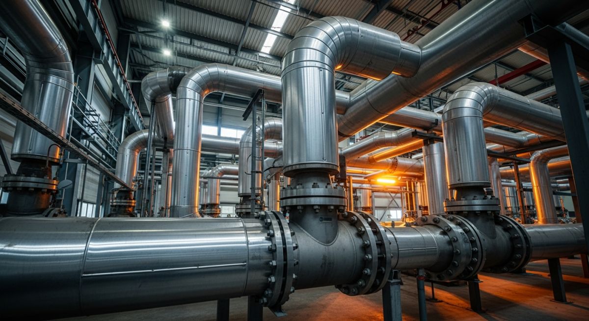
Master the fundamentals of Process Piping in 2026. Learn about ASME B31.3 codes, materials, and key differences between process piping, power piping, and plumbing.

Master the fundamentals of Process Piping in 2026. Learn about ASME B31.3 codes, materials, and key differences between process piping, power piping, and plumbing.
Comprehensive technical analysis of High Temperature and High-Pressure Piping systems. Includes 2026 ASME standards, material selection, and stress calculations.
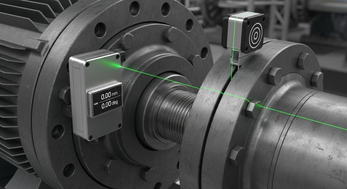
Master the procedure for Rotating Equipment Piping Alignment. Learn API 686 tolerances, flange parallelism, and pipe strain prevention for pumps and compressors in 2026.

Master ASME B31.3-2026. A complete guide to Process Piping, the new B31J stress analysis rules, wall thickness calculations, and fluid service categories.

Designing for Hydrogen? Stop using B31.3. We analyze the critical differences: Material Performance Factors (Mf), Hardness Controls, and Welding requirements for 2026 compliance.
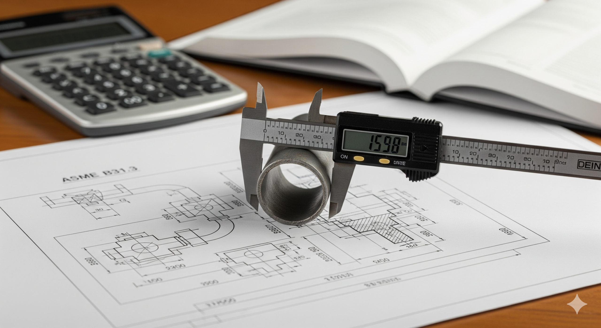
Master the ASME B31.3 pipe thickness calculation (Formula 304.1.2). Calculate ASME B31.3 pipe wall thickness with our 2026 step-by-step guide. Covers formula t=PD/2(SE+PY), mill tolerance, and schedule selection examples.

The Root Cause of Persistent Leaks: How We Overcame Flange Face Damage Leakage in Process

Master Piping Engineering: Your Complete Course Blueprint Master Piping Engineering: Your Complete Course Blueprint Imagine

Master ASME B31.3: Process Piping Code Fundamentals Master ASME B31.3: Process Piping Code Fundamentals An

Pipe thickness calculations are a critical aspect of piping engineering, ensuring the safety and longevity

Expert comparison of ASME B31.3 vs ASME B31.12 for 2026. Learn about hydrogen embrittlement, design factors, and NDE requirements for piping systems.