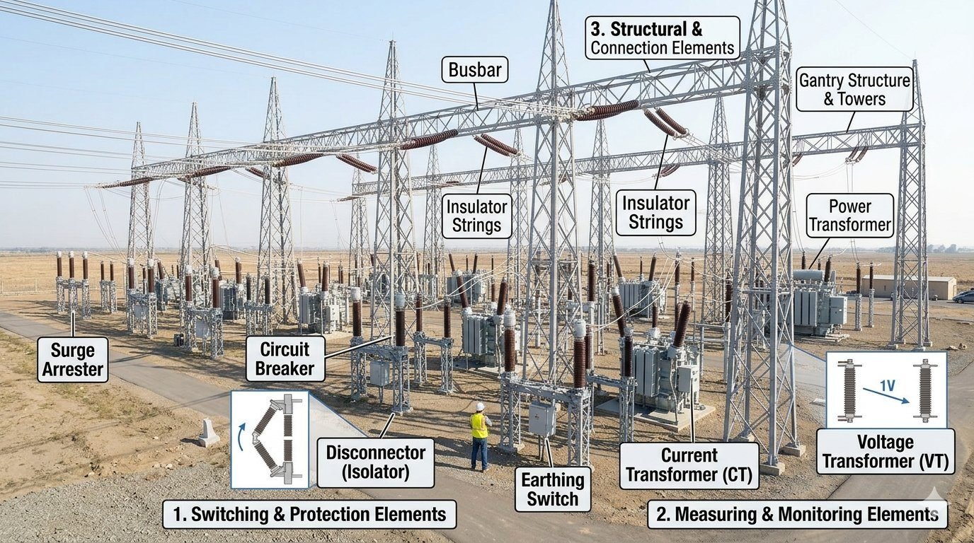
Substation Equipment Classification: Key IEC 62271 Layout Rules
Over my 20-plus years designing high-voltage switchyards, I have seen how an ambiguous substation equipment classification leads to dangerous clearance violations and unexpected protection trips during grid transients. When laying out a 132kV or 400kV bay, categorizing assets strictly by operational duty is not just a theoretical exercise; it governs mechanical interlocking, relay selectivity zones, and lattice tower loading logic.
In this deep engineering guide, I break down high-voltage switchyard assets into their three fundamental functional groups: active fault-interrupting elements, precision measurement transformers, and the physical structural backbone.
Primary Takeaways & Functional Grouping
- Switching & Protection: SF6 and vacuum circuit breakers interrupt extreme fault currents up to 63kA in under 50ms, while disconnectors establish visible safety air gaps.
- Measuring & Monitoring: Current transformers (CTs) and voltage transformers (VTs) scale down high-voltage primary values to 1A/5A and 110V inputs for numerical relays.
- Structural Backbone: Rigid tubular busbars, composite insulator strings, and steel gantries resist severe electrodynamic forces during line-to-line short circuits.
Substation Equipment Classification per IEC Standards
IEC Asset Classification Framework: Classifying electrical assets according to IEC 62271-1 establishes functional boundaries between heavy fault-clearing apparatus, secondary sensor instrument transformers, and static support structures. This systematic structure guarantees rigorous insulation coordination, physical creepage distance compliance, and predictable thermal withstand limits across high-voltage power networks.
Group 1: Switching & Protection Elements
Switching elements form the active defense shield of any electrical bay. In my experience, designing this group requires balancing rapid fault clearance speed with clear physical isolation markers for field crews.
- Circuit Breakers (CB): Governed by IEC 62271-100, circuit breakers interrupt both normal load currents and short-circuit fault currents up to 63kA. Modern high-voltage installations use sulfur hexafluoride (SF6) or clean-air vacuum interrupters capable of extinguishing high-energy arcs within 2 to 3 power cycles (40ms to 60ms).
- Disconnectors (Isolators): Designed per IEC 62271-102, disconnectors do not possess arc-quenching capability. Their purpose is to create a visible, physically verified air gap in an de-energized circuit, ensuring crew safety before maintenance begins.
- Surge Arresters (SA): Built compliant with IEC 60099-4, metal-oxide surge arresters (MOVs) act as non-linear voltage-dependent resistors. Under normal steady-state voltage, they draw microamperes of leakage current, but instantaneously transition to low impedance during lightning or switching surges to discharge high transient currents safely into the ground grid.
Group 2: Measuring & Monitoring Elements
Instrument transformers isolate sensitive secondary protection relays and digital energy meters from grid-level kilovolts and kiloamperes. Accuracy class selection dictates whether a transformer serves metering or protective relaying functions.
- Current Transformers (CT): Built to IEC 61869-2, CTs step down primary currents (e.g., 2000A) to standardized 1A or 5A secondary outputs. Protection cores (5P20 or 10P20 class) maintain linear magnetic response up to 20 times nominal current without saturating during severe external line faults.
- Voltage Transformers (VT / CVT): Designed per IEC 61869-3, inductive VTs and Capacitive Voltage Transformers (CVTs) scale line voltages (e.g., 400kV line-to-line) down to 110V or 115V secondary signals. CVTs also double as coupling units for Power Line Carrier Communication (PLCC) signals.
Group 3: Structural & Connection Elements
The physical backbone holds live conductors in place, transfers bulk power between feeder bays, and steps voltage levels for downstream grid distribution.
Busbar conductors must withstand mechanical electromagnetic bending forces generated during peak short-circuit currents. The peak electrodynamic force per unit length between parallel rigid busbars is calculated using the standard field formula:
In this relation, F_peak is the force in Newtons per meter, I_peak is the peak asymmetrical fault current in Amperes, and d is the center-to-center phase spacing in meters. When calculating conductor spans, I always verify that the mechanical section modulus of tubular aluminum busbars prevents permanent deflection under simultaneous ice, wind, and short-circuit mechanical loading.
- Power Transformers: Built according to IEC 60076, these heavy assets step primary transmission voltages down to sub-transmission or distribution levels via electromagnetic induction across oil-immersed core windings.
- Insulator Strings & Support Columns: Composite polymer or porcelain insulator stacks prevent leakage current flow to grounded steel lattice frames, selected based on nominal creepage distance requirements (typically 31mm/kV for high-pollution environments per IEC 60815).
- Gantry Towers & Overhead Structures: Galvanized steel lattice or tubular structures support overhead strain conductors, line drop jumpers, and line-side surge arresters.
Advantages & Disadvantages
Engineering Trade-Off Analysis: Implementing a standardized substation equipment classification framework optimizes system protection zones, simplifies emergency maintenance routines, and enforces strict physical safety clearances. However, segregated physical layouts demand larger switchyard real estate footprints and increase initial civil construction costs.
Design Advantages
- Enhanced Operational Safety: Grouping disconnectors separately from breakers allows visual air-gap verification before crews enter high-voltage work zones.
- Targeted Protection Zones: Positioning CTs on both sides of circuit breakers creates overlapping differential protection boundaries, eliminating blind spots.
- Streamlined Spares Management: Standardizing switching and monitoring classes per IEC 62271 allows asset inventory interchangeability across multiple switchyards.
- Optimized Insulation Coordination: Placing surge arresters directly adjacent to high-value power transformers minimizes voltage reflection peaks during lightning impulse events.
- Simplified Maintenance Access: Modular functional grouping lets technicians isolate single instrument transformers without shutting down adjacent feeder busbars.
Design Disadvantages
- Increased Land Footprint: Air-insulated switchyards utilizing full three-group physical segregation require extensive acreage to maintain phase clearances.
- Higher Initial Capital Expenditure: Individual single-function assets require more support gantries, foundation pads, and control cables than integrated hybrid units.
- Complex Mechanical Interlocking: Multi-element switching schemes require elaborate hardwired and software interlock matrices to prevent out-of-sequence operation.
- Increased Civil Foundation Works: Heavy power transformers and tall gantry structures demand deep concrete piling and extensive ground grid mats to manage earth fault currents.
- Higher Environmental Exposure: Outdoor discrete support insulators require periodic washing or silicone coating in polluted coastal regions to prevent flashovers.
Real-World Applications
Industrial Deployment Scenarios: High-voltage substation equipment classification principles adapt directly to regional transmission networks, space-constrained urban distribution hubs, and heavy industrial plant yards. Matching component specification to operational environment ensures long-term grid stability and personnel safety.
1. High-Voltage Air-Insulated Transmission Switchyards (400kV AIS)
In large outdoor regional hubs, physical separation between switching, monitoring, and busbar elements is maximized to handle immense short-circuit forces and high basic impulse levels (BIL). Rigid aluminum tubular busbars supported by porcelain post insulators connect series-mounted circuit breakers and double-break disconnectors. Outdoor metal-oxide surge arresters sit directly on incoming overhead line gantries to clip atmospheric surge voltages before they reach the main power transformer.
2. Compact Urban Gas-Insulated Substations (132kV GIS)
In dense metropolitan centers where land costs are prohibitive, functional groups are encapsulated inside grounded aluminum enclosures pressurized with SF6 gas. Circuit breakers, three-position disconnectors, and ring-core current transformers are combined inside modular bay compartments. This physical integration drastically reduces required site footprints by up to 85 percent while maintaining strict IEC functional group boundaries internally.
3. Industrial Heavy Manufacturing Plant Receiving Yards (66kV)
Industrial facilities such as steel mills and chemical refineries demand continuous power availability and fast fault clearing. These receiving switchyards feature dedicated high-accuracy metering transformers to monitor power factor and harmonic distortion. Circuit breakers incorporate fast-reclosing capabilities, and specialized disconnectors provide rapid automatic bus transfer during upstream utility voltage sags.
4. Renewable Energy Collector Substations (33kV / 220kV)
Wind and solar farm collector substations step up medium-voltage feeder collection circuits to high-voltage grid interconnections. Transformer units are fitted with specialized online gas monitoring devices, while current transformers feature multi-ratio secondary windings to maintain measurement precision across widely fluctuating seasonal generation currents.
Equipment Isolation Boundaries: High-voltage primary equipment specifications dictate the interrupting capacity, insulation withstand levels, and mechanical clearance envelopes required under international standards.
In my 20 years managing high-voltage substation switchyards, I have observed that operational failures stem directly from misaligning electrical interruption parameters with physical mechanical stress limits. Each major component category requires distinct electrical ratings and mechanical endurance thresholds to withstand short-circuit forces.
The technical parameters below outline the functional boundaries across switching, instrument transformer, and structural asset classes based on IEC 62271-1 specifications.
| Equipment Group | Primary Parameter | Standard Rating Range | Design Duty / Clearance Requirement | Governing Code |
|---|---|---|---|---|
| Circuit Breaker (Switching) | Short-Time Break Current | 31.5 kA to 63 kA (3-second rating) | Fault clearing within 20 to 40 milliseconds | IEC 62271-100 |
| Disconnector / Isolator (Switching) | Visible Air Gap Distances | 1400 mm to 3100 mm (145kV – 420kV) | Class M2 mechanical endurance (10,000 cycles) | IEC 62271-102 |
| Surge Arrester (Protection) | Nominal Discharge Current | 10 kA to 20 kA (8/20 μs impulse wave) | Continuous operating voltage (MCOV) margin | IEC 60099-4 |
| Current Transformer (Metering) | Accuracy Class & Burden | 0.2S (Metering) / 5P20 (Protection) | Secondary output 1A or 5A, knee-point voltage matching | IEC 61869-2 |
| Voltage Transformer (Metering) | Voltage Factor & Accuracy | 1.2 continuous / 1.5 for 30s (Class 0.2) | Secondary output 110V phase-to-phase insulation | IEC 61869-3 |
| Busbars & Structural Supports | Electrodynamic Mechanical Stress | Peak withstand up to 160 kA peak | Deflection limits under short-circuit and wind shear | IEC 60865-1 |
Proper selection requires evaluating the interaction between maximum prospective short-circuit current and structural withstand strength. I recheck these parameters whenever a grid expansion increases system fault levels above original baseline designs.
Substation Component Mapping: System functional groups correlate physical equipment design with specific mechanical load envelopes and international standardization codes.
Managing substation engineering documentation demands clear categorization between active interrupting devices, passive measurement sensors, and load-bearing structures. I utilize this structural matrix during detailed design reviews to ensure that material specifications align across electrical and civil engineering disciplines.
| Functional Class | Asset Entity | Substation Bay Role | Material / Insulation Medium | Standard Baseline |
|---|---|---|---|---|
| Switching & Protection | SF6 / Vacuum Circuit Breaker | Interrupt load and fault currents instantly | Sulfur Hexafluoride Gas or Vacuum Interrupter | IEC 62271-100 |
| Switching & Protection | Center-Break Disconnector | Provide visible air isolation for maintenance | Galvanized Steel / Aluminum Contact Arms | IEC 62271-102 |
| Switching & Protection | Metal-Oxide Surge Arrester | Divert transient overvoltages to earth grid | Zinc Oxide (ZnO) Blocks in Silicone Housing | IEC 60099-4 |
| Measuring & Monitoring | Current Transformer (CT) | Step down primary current for protective relays | Oil-Impregnated Paper or Synthetic Resin | IEC 61869-2 |
| Measuring & Monitoring | Capacitor Voltage Transformer | Step down system voltage and supply carrier signals | Capacitor Stacks in Oil-Filled Porcelain | IEC 61869-5 |
| Structural & Connection | Rigid Tubular Aluminum Busbar | Form main electrical distribution backbone | 6063-T6 Aluminum Alloy Tube | IEC 60865-1 |
| Structural & Connection | Lattice Steel Gantry Structure | Support overhead lines and equipment drops | Structural Steel per ASTM A36 / ISO 630 | ASCE Manual 113 |
This entity matrix serves as a cross-reference tool for design coordinators to ensure interface compatibility between civil foundation anchor bolts, support structures, and active primary equipment.
Field Quality Assurance: Systematic site inspection protocols verify phase clearances, mechanical interlocks, SF6 gas integrity, and ground continuity prior to energization.
In my years supervising field commissioning, skipped checklist items are the single primary cause of catastrophic flashovers during initial energization. A structured pre-commissioning walkthrough guarantees that physical alignment, electrical clearances, and mechanical interlocks comply strictly with site drawings.
Pre-Energization Site Inspection Protocol
1. Switching & Protection Assets
- SF6 Gas Pressure: Verify gas density monitoring gauges match factory temperature-compensated fill curves.
- Contact Alignment: Check disconnector jaw alignment and measure contact resistance across main blades.
- Mechanical Interlocks: Confirm the mechanical interlock prevents disconnector operation while the associated circuit breaker is closed.
- Surge Arrester Grounding: Inspect discharge counters and verify high-frequency copper earth leads route straight to the main grid without sharp bends.
2. Measuring & Monitoring Assets
- CT Secondary Loops: Perform polarity checks and verify that all unused CT secondary cores are shorted and grounded.
- VT Secondary Circuits: Check neutral grounding at a single common point to avoid circulating earth currents.
- Insulation Resistance: Record megger test readings for CT/VT primary windings relative to tank ground per IEEE C57.13 limits.
3. Structural & Connection Components
- Phase Clearance Verification: Measure minimum phase-to-phase and phase-to-earth air distances against IEC 61936-1 tables.
- Busbar Hardware Torque: Verify calibrated torque wrench values on all terminal clamps and Belleville washer stacks.
- Insulator Cleanliness: Inspect porcelain and composite insulator sheds for surface cracking, chips, or industrial contamination.
- Gantry Earthing: Verify double-ground bonding connections from lattice structure legs to the earth mat grounding riser.
I recommend keeping signed physical copies of this checklist logged in the substation control room records. Field verification signed off by a qualified lead engineer provides an indispensable audit trail before authorization for initial back-feeding.
Field Case Study: Real-World Application
Interlock Coordination Failure: Field analysis of a 230 kV switchyard flashover during routine line isolation procedures.
During a scheduled maintenance outage at a major industrial 230 kV substation, an operator attempted to open an line disconnector under load. The mechanical interlock between the main circuit breaker and the disconnector failed to engage, generating a massive open-air arc that spanned across adjacent bus phases.
Incident Root Cause Breakdown:
An investigation revealed multiple physical and procedural oversights across equipment maintenance protocols:
- Mechanical Linkage Wear: The physical interlock pin on the disconnector operating mechanism was sheared due to excessive force applied during prior operations.
- Defective Auxiliary Contact: The circuit breaker auxiliary switch failed to signal its closed state to the remote electrical interlocking logic.
- Surge Protection Position: Surge arresters were installed upstream of the disconnector, leaving the open-air gap unprotected against switching surges.
- Inadequate Phase Spacing: Tubular busbar spacing did not account for dynamic plasma expansion during high-voltage air arcing.
Engineering Remediation & Measurable System Improvements:
I led the failure recovery team to implement corrective design modifications compliant with IEC 62271-102 standards:
- Dual-Redundant Interlocking: Integrated fail-safe hardwired electrical solenoid interlocks alongside mechanical key-exchange (Castell key) systems.
- Optical Contact Monitoring: Installed fiber-optic position sensors on circuit breaker main contacts to verify physical opening independent of auxiliary switches.
- Arrester Relocation: Positioned zinc-oxide surge arresters directly at line entrance gantries to clamp switching overvoltages.
- Zero Interlock Breaches: Achieved 100% operation safety without a single interlocking logic failure across 36 months of subsequent field operations.
In my experience, mechanical interlocks must never be relied upon as the sole line of defense against accidental load break events. Combining physical keys, hardwired electrical control permits, and automated SCADA interlocking logic creates the required defense-in-depth safety standard for high-voltage operational yards.
Frequently Asked Engineering Questions
How does IEC 62271 define the main substation equipment classification groups?
- Switching & Protection Elements: Circuit breakers, disconnectors, and surge arresters for dynamic fault clearance and overvoltage clamping.
- Measuring & Monitoring Elements: Instrument transformers (CTs and VTs) that scale primary voltages and currents down to relay levels.
- Structural & Connection Elements: Busbars, gantries, insulators, and power transformers establishing the physical transmission matrix.
What is the key operational distinction between a circuit breaker and a disconnector?
- Circuit Breakers: Intercept short-circuit fault currents within milliseconds under full system load, using arc-quenching media like SF6 or vacuum.
- Disconnectors (Isolators): Operate strictly under zero-load conditions to create a visible physical air gap, guaranteeing safe isolation for field crews.
- Mechanical Interlocking: Trapped-key or electrical interlocks block disconnector movement until the series breaker is verified open.
How do instrument transformers maintain measurement accuracy while protecting relays?
- Current Transformers (CTs): Step down heavy primary amperes to standardized 1A or 5A secondary outputs for protection relays.
- Voltage Transformers (VTs): Convert high transmission voltages down to safe secondary levels, typically 110V, per IEEE C57.13.
- Dielectric Isolation: High-grade paper-oil or resin insulation barriers keep control room equipment fully isolated from high-voltage surges.
Why are surge arresters placed immediately adjacent to power transformers?
- Non-Linear Zinc Oxide Blocks: Maintain high resistance during standard voltage but drop to low impedance during overvoltage events.
- Nanosecond Response: Divert lightning impulses and switching surges safely to the grounding grid within fractions of a microsecond.
- Insulation Coordination: Keeps transient voltage peaks below the transformer basic impulse insulation level (BIL) per IEC 60071.
How do structural and connection elements withstand severe short-circuit forces?
- Busbar Ratings: Rigid aluminum or copper tubes sized to withstand dynamic mechanical stress and transient thermal spikes.
- Gantry Towers: Heavy steel structures designed to anchor high-tension incoming lines under severe ice and wind loading.
- Insulator Columns: Composite or porcelain post insulators provide high cantilever strength while preventing current leaks to earth.
Complete Course on
Piping Engineering
Check Now
Key Features
- 125+ Hours Content
- 500+ Recorded Lectures
- 20+ Years Exp.
- Lifetime Access
Coverage
- Codes & Standards
- Layouts & Design
- Material Eng.
- Stress Analysis
