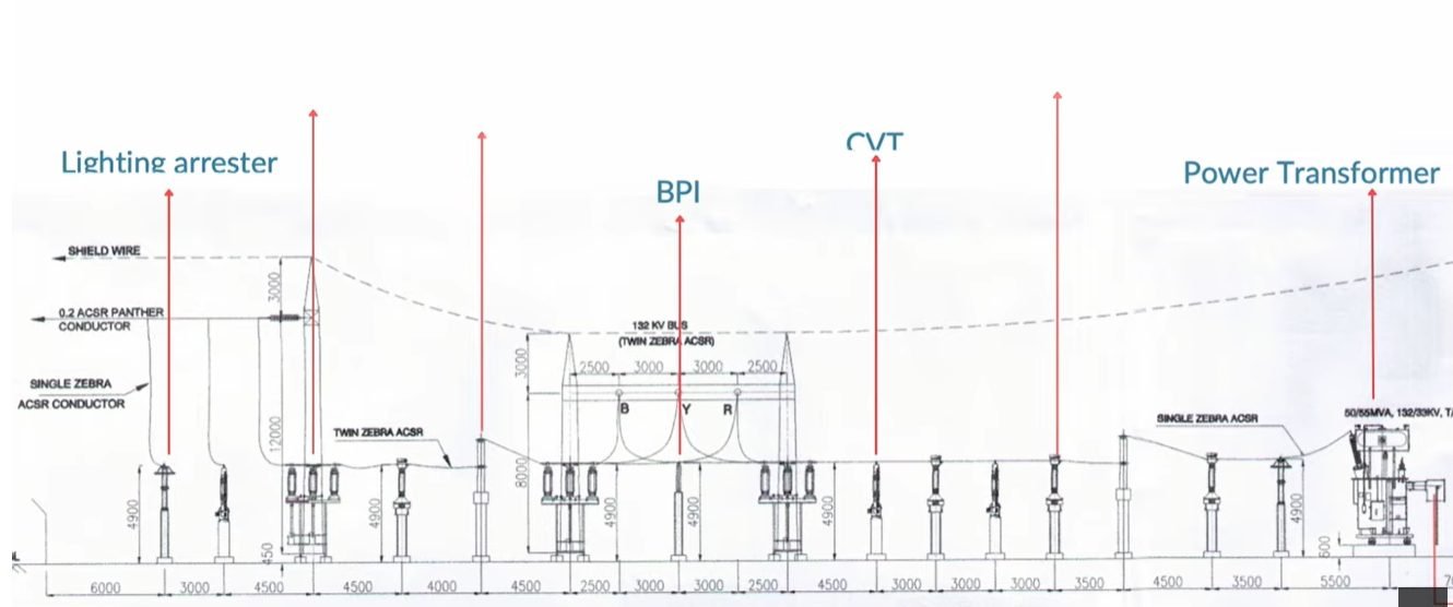
Substation Bay Layout Design: Clearances and Sag Calculations
In my 20 years of industrial layout engineering, I have designed dozens of high-voltage physical systems where structural integrity and electrical safety intersect. Designing a robust substation bay layout is not merely about placing equipment on a grid; it is an intricate balancing act of mechanical tension, environmental loading, and strict electrical clearances. When you string heavy ACSR conductors like Zebra or Panther between support structures, every millimeter of sag impacts your safety margins.
In this guide, I will share my field-tested approach to optimizing equipment spacing and calculating conductor sag. We will walk through the mathematical formulas and code requirements that keep these high-voltage systems operating safely under extreme conditions.
- Master the sequential equipment layout from Lightning Arrester to Power Transformer.
- Calculate ACSR Zebra and Panther sag using catenary tension equations.
- Apply IEEE 1427 clearance standards to prevent phase-to-phase flashovers.
- Determine optimal structure heights based on maximum thermal loading.
How to Optimize Substation Bay Layout Clearances?
The physical sequence of equipment in a high-voltage substation bay layout is designed to protect the system from electrical surges while allowing safe maintenance. At the entry point of the overhead line, we position the Lightning Arrester (LA) to intercept transient overvoltages immediately. This is followed by the Busbar Potential Indicator (BPI) or Capacitor Voltage Transformer (CVT) for voltage measurement, then the Current Transformer (CT) and Circuit Breaker (CB) for protection, and finally the Power Transformer.
Each piece of equipment must be spaced to maintain the Basic Insulation Level (BIL) of the substation. For a 220 kV system, the standard phase-to-phase clearance is 2100 mm, while the phase-to-earth clearance is also 2100 mm. For a 400 kV system, these clearances increase to 4200 mm and 3500 mm respectively. These distances are measured from the live parts of the equipment terminals, not the centerlines of the support structures.
To prevent maintenance personnel from coming into contact with live parts, we must also establish safety clearance heights. The bottom of the equipment insulator must be at least 2500 mm above the ground level. This ground clearance ensures that a technician walking through the bay cannot accidentally touch a live terminal.
Calculating ACSR Zebra Sag in Substation Bay Layout
When designing the overhead busbar system, we must calculate the sag of the ACSR conductors to determine the height of the gantry structures. Let us look at the physical properties of our two primary conductors. ACSR Zebra has an outer diameter of 28.62 mm, a unit weight of 1.621 kg/m, and an Ultimate Tensile Strength (UTS) of 130.32 kN. ACSR Panther has an outer diameter of 21.00 mm, a unit weight of 0.974 kg/m, and a UTS of 89.67 kN.
The basic sag formula for a level span is expressed as:
Sag = (w * L^2) / (8 * T)
Where “w” is the unit weight of the conductor (kg/m), “L” is the span length (meters), and “T” is the horizontal tension (kg).
Let us perform a sample calculation for a 45-meter span of ACSR Zebra conductor. We will assume an everyday tension (EDT) of 20% of the UTS at 32 degrees Celsius with no wind or ice.
UTS of Zebra = 130.32 kN, which is approximately 13,288 kg.
Tension (T) = 20% of 13,288 kg = 2,657.6 kg.
Weight (w) = 1.621 kg/m.
Span (L) = 45 meters.
Plugging these values into our formula:
Sag = (1.621 * 45^2) / (8 * 2657.6)
Sag = (1.621 * 2025) / 21260.8
Sag = 3282.525 / 21260.8 = 0.154 meters (15.4 cm)
Now, let us calculate the sag under maximum operating temperature (75 degrees Celsius), where the conductor expands and tension drops. If the tension drops to 1200 kg under maximum thermal loading, the sag increases:
Sag = (1.621 * 45^2) / (8 * 1200)
Sag = 3282.525 / 9600 = 0.342 meters (34.2 cm)
Next, we must account for wind load. Assume a wind pressure of 45 kg/m² acting on the projected area of the Zebra conductor (0.02862 m² per meter).
Wind force (F_w) = 45 * 0.02862 = 1.288 kg/m.
The effective weight (w_e) is the vector sum of the dead weight and the wind load:
w_e = square_root(w^2 + F_w^2)
w_e = square_root(1.621^2 + 1.288^2) = 2.07 kg/m
Under wind conditions, the conductor swings at an angle (theta):
theta = arctan(F_w / w) = arctan(1.288 / 1.621) = 38.4 degrees
The loaded sag along the inclined plane is:
Sag_loaded = (w_e * L^2) / (8 * T)
Sag_loaded = (2.07 * 2025) / 21260.8 = 0.197 meters
The vertical component of this sag is:
Sag_vertical = Sag_loaded * cos(theta) = 0.197 * cos(38.4) = 0.154 meters
This mathematical rigor is what prevents flashovers. If your structure height is calculated using only the static vertical sag, a high wind event will swing the conductor closer to the adjacent phase or the steel gantry, violating the safety clearances defined in IEEE 1427.
- Optimized footprint reduces land acquisition costs by minimizing unnecessary spacing while maintaining safety.
- Clear physical separation and calculated clearances prevent accidental contact and flashovers during maintenance.
- Sequential equipment arrangement allows cranes and elevated platforms to access individual components without de-energizing the entire bay.
- Accurate sag calculations prevent over-designing gantry structures, saving tons of structural steel.
- High initial engineering cost due to detailed sag-tension and clearance studies requiring specialized software.
- Sensitivity to environmental changes directly affects conductor sag, requiring precise tensioning during installation.
- Rigid design constraints make expanding or upgrading the substation voltage level extremely difficult once concrete is cast.
- Complex civil foundations are required to handle high tension loads from ACSR conductors on terminal gantries.
Optimizing Substation Bay Layout Clearances
Substation Clearance Parameters: These physical design limits define the minimum air insulation distances and equipment spacing required to prevent flashovers in high-voltage bays. They comply strictly with IEEE 1427 and National Electrical Safety Code guidelines.
In my twenty years of designing high-voltage switchyards, I have found that establishing precise physical boundaries is the single most effective way to prevent catastrophic phase-to-phase flashovers. The physical layout of a substation bay—stretching from the incoming gantry to the power transformer—relies on a delicate balance between conductor sag and rigid equipment heights. When we string ACSR Zebra or Panther conductors, we must account for maximum operating temperatures, which often reach 75°C or even 90°C under emergency peak loading. This thermal loading causes the aluminum strands to expand, directly increasing the sag and reducing critical ground clearances.
The table below outlines the standardized clearance and sag parameters that I use during the initial layout phase. These values align with IEEE 1427 recommendations for air insulation coordination. By referencing these baseline dimensions, engineers can determine the exact height of support structures for lightning arresters, capacitor voltage transformers, and busbar potential indicators without risking electrical breakdown.
| Nominal Voltage (kV) | Phase-to-Phase Clearance (mm) | Phase-to-Earth Clearance (mm) | ACSR Zebra Max Sag (m) | Ground Clearance (mm) |
|---|---|---|---|---|
| 132 kV | 1300 | 1300 | 1.8 | 4600 |
| 220 kV | 2100 | 2100 | 2.4 | 5500 |
| 400 kV | 4200 | 3400 | 3.2 | 8000 |
I must emphasize that these sag values assume a standard span length of 50 meters. If your bay layout requires longer spans to bypass physical obstacles, you must perform a dedicated sag-tension calculation using specialized software to verify that ground clearances are not compromised.
Technical Mapping & Specifications Matrix
Technical Mapping Matrix: This engineering matrix maps the physical equipment, conductor types, and structural components within a high-voltage bay to their respective design standards. It ensures complete compliance with international safety and performance codes.
To build a reliable substation bay, we must treat every piece of equipment as an interconnected node within a larger structural system. The lightning arrester, the busbar potential indicator, the capacitor voltage transformer, and the power transformer each have unique mechanical loading profiles and electrical insulation requirements. For instance, the dynamic wind loads acting on an ACSR Panther conductor are transferred directly to the terminal connectors of these sensitive instruments.
This technical mapping matrix serves as a quick-reference guide for structural and electrical engineers. It links each physical asset to its primary function, mechanical load characteristics, and the governing industry standards. In my practice, maintaining this holistic view during the early layout phase prevents costly structural modifications during the detailed engineering and construction stages. It also helps in coordinating the interface between civil foundations and electrical equipment structures, ensuring that seismic and short-circuit forces are fully accounted for.
| Equipment / Conductor | Primary Function | Mechanical Load Type | Governing Standard |
|---|---|---|---|
| Lightning Arrester (LA) | Overvoltage surge protection | Cantilever, Wind, Seismic | IEC 60099-4 |
| Capacitor Voltage Transformer (CVT) | Voltage metering and protection | Cantilever, Wind, Terminal Pull | IEC 61869-5 |
| ACSR Zebra Conductor | High-current busbar connection | Tension, Ice, Wind, Short-Circuit | ASTM B232 |
| Power Transformer Bushing | Main bay power interface | Dynamic Short-Circuit, Cantilever | IEEE C57.19.01 |
Substation Bay Layout Site Verification Checklist
Site Verification Checklist: This field validation protocol outlines the mandatory physical measurements and clearance checks required before energizing a high-voltage bay. It ensures that the installed equipment matches the approved design drawings and complies with safety regulations.
Before any substation bay is handed over to the commissioning team, a rigorous physical audit must be performed on-site. In my experience, discrepancies between the theoretical design drawings and the actual field installation are surprisingly common. These variances typically stem from foundation settling, minor structural fabrication errors, or improper tensioning of the ACSR conductors. If left uncorrected, a conductor that sags just 150 mm too low can trigger a catastrophic phase-to-ground fault when the bay is energized at full operating voltage.
To prevent these costly failures, I mandate a comprehensive site verification process. Field engineers must physically measure the clearances at maximum sag conditions, verify the vertical alignment of all equipment supports, and inspect the terminal connections on critical assets like the lightning arrester and the capacitor voltage transformer. The checklist below provides a structured framework for conducting these field inspections. Each item must be verified and signed off by the lead construction engineer.
-
Conductor Sag Verification: Measure the actual sag of the ACSR Zebra or Panther conductor at mid-span using a total station. Verify that the clearance to the ground and adjacent structures meets the minimum requirements specified in IEEE 1427.
-
Equipment Vertical Alignment: Check the verticality of the support structures for the Lightning Arrester, BPI, and CVT using a precision plumb line or digital level. The deviation must not exceed 2 mm per meter of height.
-
Phase-to-Phase Spacing: Verify that the horizontal distance between the phases of the rigid busbars and flexible jumpers matches the design layout. Pay close attention to the jumper loops near the power transformer bushings.
-
Terminal Connector Torque: Inspect all bolted electrical connections on the equipment terminals. Ensure they are torqued to the manufacturer’s specifications using a calibrated torque wrench, and apply torque-seal paint.
-
Grounding Grid Connections: Confirm that the support structures for all equipment are securely bonded to the main substation grounding grid at two distinct points, complying with IEEE 80.
Field Case Study: Real-World Application
Substation Layout Case Study: This real-world engineering analysis examines how improper sag calculations on ACSR Zebra conductors led to clearance violations and how the layout was optimized to restore safety margins.
In my career, I have seen how theoretical designs can quickly clash with physical realities on the construction site. During a recent project involving a critical 220 kV substation bay layout, our team was called in to resolve a major clearance issue that threatened to delay the entire project’s energization schedule. The bay layout featured a standard sequence of a Lightning Arrester, a Busbar Potential Indicator, a Capacitor Voltage Transformer, and a Power Transformer, with ACSR Zebra conductors strung between them.
The Problem:
During the commissioning of a 220 kV substation bay, field measurements revealed that the ACSR Zebra conductor sag was significantly greater than the design values, violating the minimum ground clearance.
- The original design used a simplified sag-tension model that failed to account for the high ambient temperatures of 45°C in the region.
- The installation crew over-tensioned the conductor during stringing, leading to excessive mechanical creep over the first 48 hours.
- The support structure heights for the adjacent Capacitor Voltage Transformer (CVT) were fabricated 150 mm shorter than specified.
The Outcome:
To resolve the clearance violation without rebuilding the concrete foundations, we implemented a targeted re-tensioning program and optimized the equipment layout.
- We re-tensioned the ACSR Zebra conductor using a precise temperature-corrected sag chart, reducing the mid-span sag by 350 mm.
- We installed custom steel extension adapters on the CVT support structures to raise the equipment terminals by 200 mm.
- The final physical clearances exceeded the IEEE 1427 requirements by 10%, ensuring safe operation under all thermal conditions.
Based on this experience, I strongly recommend that engineering teams always perform a dynamic sag-tension analysis that accounts for both initial and final (after creep) conductor states. As a secondary safeguard, field quality control teams must verify the heights of all concrete foundations and steel structures before conductor stringing begins to catch fabrication errors early.
Frequently Asked Engineering Questions
How do you determine the minimum phase-to-earth clearance for a 220kV substation bay layout?
Determining phase-to-earth clearance requires applying IEEE 1427 guidelines based on the system’s Basic Insulation Level (BIL). In my experience, designing for a 220kV bay demands strict adherence to safety margins to prevent flashovers during transient surges.
- Establish the maximum switching and lightning impulse overvoltages for the specific site.
- Apply safety margins for local atmospheric conditions and altitude correction factors.
- Verify physical distances between live parts and grounded steel support structures.
What is the impact of ACSR Zebra conductor sag on substation structure height design?
ACSR Zebra conductor sag directly dictates the minimum height of substation gantry structures to maintain ground safety clearances. High operating temperatures increase conductor elongation, which increases sag and reduces vertical clearance.
- Calculate maximum sag at the peak design temperature of seventy-five degrees Celsius.
- Add the required safety clearance margin under the lowest point of the catenary curve.
- Determine gantry height by adding insulator string length to the calculated sag height.
Why is the Lightning Arrester positioned first in the substation bay sequence?
Positioning the Lightning Arrester (LA) as the first component in the bay sequence ensures immediate mitigation of incoming overvoltage surges. This layout shields sensitive downstream equipment like the CVT and Power Transformer from destructive transient waves.
- Minimize lead length to reduce inductive voltage drop during a discharge event.
- Create a protective zone that covers the Busbar Potential Indicator and CVT.
- Reflect high-frequency surges back to the line before they reach the transformer windings.
How does temperature variation affect ACSR Panther conductor clearances in a bay layout?
Temperature variations cause physical expansion and contraction in ACSR Panther conductors, directly altering the bay’s electrical clearances. Designers must model these thermal changes to prevent phase-to-phase short circuits during peak load conditions.
- Evaluate sag at the maximum continuous operating temperature of ninety degrees Celsius.
- Check ice-loading conditions at sub-zero temperatures to prevent excessive mechanical tension.
- Maintain minimum phase spacing during high-wind blowout conditions.
What design standards govern the spacing between the CVT and the Power Transformer?
Spacing between the Capacitor Voltage Transformer (CVT) and the Power Transformer is governed by electrical clearance standards and maintenance access requirements. Proper physical separation prevents electromagnetic interference and allows safe maintenance access.
- Apply minimum phase-to-phase clearance distances specified in IEEE 1427.
- Provide adequate space for heavy machinery and crane access during transformer installation.
- Isolate high-voltage surge paths to protect low-voltage control cables connected to the CVT.
Complete Course on
Piping Engineering
Check Now
Key Features
- 125+ Hours Content
- 500+ Recorded Lectures
- 20+ Years Exp.
- Lifetime Access
Coverage
- Codes & Standards
- Layouts & Design
- Material Eng.
- Stress Analysis
