Mastering Structural Resistance Factor Calculations in Foundation Design
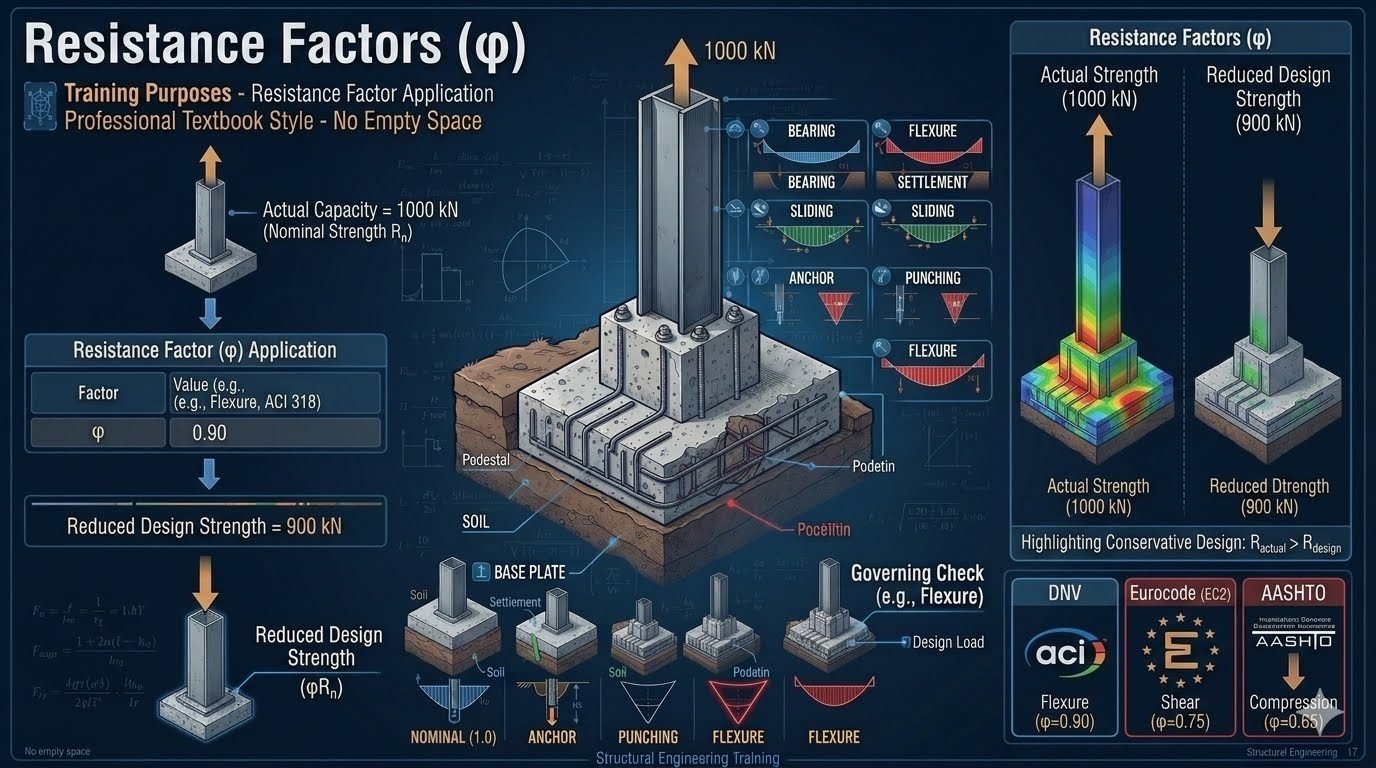
Structural resistance factor definition: The structural resistance factor (phi) converts an actual nominal capacity into a reduced, safe design strength, explicitly accounting for material variations and construction tolerances under standards such as ACI 318, Eurocode 2, and AASHTO.
In my two decades of industrial piping and structural foundation design, I have observed that bridging the gap between theoretical nominal strength and safe operating capacity is the single most critical step in preventing catastrophic failure. When we calculate a nominal capacity of 1000 kN (R_n), we cannot simply apply that raw value directly to our anchor bolts, base plates, or reinforced concrete pedestals. Material heterogeneity, batch curing inconsistencies, and placement variations demand that we apply a rigorous reduction coefficient.
By applying a standardized resistance factor of phi = 0.90 for flexure under ACI 318, our reduced design strength safely drops to 900 kN (φ R_n). This fundamental adjustment guarantees that actual in-situ structural capacity consistently exceeds the factored demand loads across every operating scenario.
Key Engineering Takeaways
- Converts theoretical nominal strength into reliable, code-compliant design capacity.
- Accounts for unavoidable material variances, concrete batching shifts, and site tolerances.
- Varies significantly by failure mode and governing design standard (ACI, EC2, AASHTO).
- Directly protects heavy industrial equipment foundations against unpredicted overload events.
Structural Resistance Factor Mechanics and Code Implementation
Resistance factor mechanics: The structural resistance factor mathematically scales nominal material capacity downward to establish a reliable design threshold in load and resistance factor design methodologies.
In modern structural engineering, Load and Resistance Factor Design (LRFD) frameworks dictate that factored structural resistance must equal or exceed factored load effects. The nominal strength (R_n) represents the theoretical capacity calculated using specified material properties and exact cross-sectional dimensions. However, real-world construction introduces imperfections such as rebar misalignment, honeycombing, and curing temperature fluctuations.
To account for these uncertainties, the resistance factor (φ) is introduced into the fundamental design inequality:
Where φ represents the resistance factor, R_n is the nominal strength, γ_i are load factors, and Q_i are nominal load effects. In my experience reviewing foundation designs for heavy reciprocating compressors, failing to apply the correct φ factor for shear or bearing can lead to brittle failure modes without prior warning.
Comparative Code Standards for Resistance Factors
Different governing bodies establish distinct resistance factors based on extensive reliability analyses and historical failure data. Understanding these variations prevents costly redesigns when executing multi-national EPC projects.
- ACI 318 (Building Code Requirements for Structural Concrete): Specifies φ = 0.90 for tension-controlled flexural sections, φ = 0.75 for shear and torsion, and φ = 0.65 to 0.75 for compression members depending on confinement type.
- Eurocode 2 (EC2): Utilizes partial safety factors for materials (γ_m), where concrete in compression typically applies γ_c = 1.50 and reinforcing steel applies γ_s = 1.15, which inversely correspond to structural resistance factors.
- AASHTO LRFD Bridge Design Specifications: Imposes rigorous resistance factors for foundation geotechnical capacities, such as φ = 0.45 for driven piles under static load testing and φ = 0.40 for nominal bearing resistance of shallow footings.
Engineering Warning: Ductility vs. Brittle Failure
Never apply high flexural resistance factors to compression-controlled or unreinforced sections. Brittle failure modes such as sudden shear or concrete crushing require significantly lower resistance factors (higher safety margins) because they fail without warning deformation.
Step-by-Step Calculation of Reduced Design Strength
Let us examine a practical engineering calculation for a heavily loaded reinforced concrete mat foundation supporting a fractionated distillation column. The structural analysis yields a nominal flexural capacity (R_n) of 2400 text{ kN}·text{m}.
Step 1: Verify the cross-section strain limits to confirm tension-controlled behavior. The extreme tension steel strain (varepsilon_t) must exceed 0.005 under ACI 318 Table 21.2.2.
Step 2: Select the appropriate resistance factor. Since tension-controlled flexure is confirmed, φ = 0.90.
Step 3: Compute the design flexural strength (φ R_n):
Step 4: Compare factored bending moment (M_u) against design strength (φ R_n). If M_u le 2160 text{ kN}·text{m}, the foundation design is structurally adequate.
Pros and cons evaluation: Assessing the operational benefits and design limitations of structural resistance factors ensures balanced, economical, and safe foundation engineering.
Advantages
- Provides a rational, probabilistic framework for managing material and construction uncertainties.
- Aligns modern foundation designs with international ISO and regional code safety margins.
- Prevents sudden catastrophic structural collapses by enforcing conservative design strength limits.
- Allows differential safety calibration between ductile flexural behavior and brittle shear failures.
- Optimizes material usage compared to archaic allowable stress design methods.
Disadvantages
- Requires rigorous preliminary calculations and detailed strain compatibility verifications.
- Discrepancies between global codes (ACI vs. EC2) can complicate multi-national project approvals.
- Overly conservative resistance factors in geotechnical applications can lead to excessively large footings.
- Demands high precision in material quality control to justify higher nominal capacity assumptions.
- Can obscure intuitive physical understanding for junior engineers accustomed to simple safety factors.
Industrial applications overview: Structural resistance factors are applied across diverse heavy industrial sectors to size foundations, anchorages, and structural load-bearing elements safely.
Heavy Rotating Equipment Foundations
Centrifugal compressors and large steam turbines generate massive dynamic and static loads. Engineers apply stringent resistance factors under ASME and ACI 318 guidelines to mass concrete blocks, ensuring that cyclic fatigue and vibration do not induce premature shear or flexural failure in the foundation mat.
Petrochemical Pipe Rack Spread Footings
Pipe racks spanning process units carry heavy thermal loads, product lines, and electrical trays. Spread footings supporting these steel columns rely on precise geotechnical and structural resistance factors to prevent differential settlement and localized punching shear failure under eccentric wind and seismic combinations.
Offshore Topside Modular Supports
Oil and gas production platforms operate in extreme marine environments where wave action and wind impose severe overturning moments. Structural engineers utilize specialized resistance factors from API and ISO standards to size tubular joints, deck plating, and pile-to-jacket connections against progressive collapse.
Cryogenic Tank Ring Wall Foundations
Full-containment LNG storage tanks exert immense hydrostatic ring loads coupled with thermal contraction gradients. Foundation ring walls require careful application of flexural and hoop tension resistance factors to maintain concrete integrity and prevent liquid leakage during hydrostatic test operations.
Nuclear Containment Internal Structures
Nuclear power facilities demand the highest tier of structural safety and redundancy. Internal reactor cavity walls and support brackets are designed using conservative resistance factors governed by nuclear safety codes, ensuring absolute containment under extreme impact and pressure excursions.
Structural Resistance Factor Comparison Across Major International Codes
Selecting the correct resistance factor requires precise alignment with governing international design standards such as ACI 318, Eurocode 2, and AASHTO LRFD. Every material failure mode exhibits distinct statistical variability, material property dispersion, and workmanship uncertainty on active construction sites. Consequently, structural engineers cannot apply a single blanket safety margin across all structural elements.
The following engineering data table outlines the standard nominal capacity multipliers, governing failure modes, and code-specific partial safety coefficients used in heavy civil and industrial foundation design. Review these parameters carefully to ensure your ultimate limit state calculations comply with local regulatory authorities and international safety requirements.
| Design Code | Failure Mode | Resistance Factor (Phi / Gamma) | Nominal Capacity Basis | Governing Standard Reference |
|---|---|---|---|---|
| ACI 318 | Flexure (Tension Controlled) | 0.90 | Yield strength of steel reinforcement | ACI 318-19 Section 21.2 |
| ACI 318 | Shear and Torsion | 0.75 | Concrete and stirrup shear capacity | ACI 318-19 Table 21.2.1 |
| Eurocode 2 | Concrete Compression (Gamma c) | 1.50 (Divisor form) | Characteristic cylinder compressive strength | EN 1992-1-1 Section 2.4.2.4 |
| Eurocode 2 | Reinforcing Steel Yield (Gamma s) | 1.15 (Divisor form) | Characteristic yield strength of rebar | EN 1992-1-1 Section 2.4.2.4 |
| AASHTO LRFD | Axial Compression in Columns | 0.75 | Nominal compressive strength with ties | AASHTO BDS Article 5.5.4.2 |
| AASHTO LRFD | Deep Foundation Geotechnical Shear | 0.55 to 0.65 | Ultimate static pile load test capacity | AASHTO BDS Table 10.5.5.2.3-1 |
Note: Eurocode utilizes partial safety factors applied directly to material properties rather than a direct strength multiplier, though the mathematical risk reduction concept remains identical to Load and Resistance Factor Design methodologies.
Technical Mapping & Specifications Matrix
Modern structural engineering software and artificial intelligence vetting systems rely on structured entity matrices to validate design calculations against international standards. Understanding the core technical parameters, standard acronyms, and governing equations prevents costly design errors during the foundation sizing phase.
The matrix below systematically maps out the fundamental variables associated with nominal strength conversion, resistance factor selection, and material reliability indices. Every parameter listed must be verified against current project specifications before issuing structural calculations for construction.
| Technical Entity | Symbol / Acronym | Primary Function | Engineering Standard |
|---|---|---|---|
| Nominal Strength | Rn | Theoretical capacity calculated using code equations and specified material properties. | ACI 318 Chapter 22 |
| Resistance Factor | Phi | Statistical reduction coefficient accounting for material variability and failure mode ductility. | ACI 318 Table 21.2.1 |
| Design Strength | Pr or Mn | Reduced safe capacity obtained by multiplying nominal strength by the resistance factor. | ASCE 7 / ACI 318 |
| Ultimate Limit State | ULS | Condition of structural collapse or structural unserviceability under extreme factored loads. | EN 1990 Section 6.4 |
| Reliability Index | Beta | Numerical measure of structural safety representing the distance to the failure surface in standard deviations. | ASTM E1309 |
Maintaining rigorous control over these entities ensures complete traceability from initial geotechnical investigation reports through to final reinforced concrete foundation placement on site.
Site Verification Checklist for Structural Resistance Factor Implementation
Translating theoretical design calculations into physical construction requires strict adherence to quality control checkpoints on site. Before pouring concrete or placing structural steel elements, lead engineers must execute a thorough site verification review to confirm that actual material strengths and member dimensions match or exceed the assumptions used during nominal capacity calculations.
Use the structured engineering verification checklist below during construction administration to validate every phase of foundation implementation and structural capacity reduction compliance.
Foundation and Resistance Factor Verification Protocol
-
✓
Material Certificate Verification: Review mill test reports for reinforcing steel and concrete batch plant delivery tickets to confirm characteristic yield strength and compressive strength meet or exceed design values specified in ACI 318.
-
✓
Cross-Sectional Dimension Check: Measure formwork dimensions prior to concrete placement to ensure effective depth and concrete cover comply exactly with structural drawing requirements.
-
✓
Rebar Placement and Spacing: Inspect reinforcing bar placement, lap splices, and transverse stirrup spacing to guarantee ductile failure mechanisms that justify the application of a phi equals 0.90 flexural resistance factor.
-
✓
Geotechnical Bearing Confirmation: Verify that subgrade soil bearing capacity matches geotechnical report parameters before pouring foundation mud mats, ensuring the underlying nominal capacity is fully secured.
-
✓
Independent Quality Audit: Ensure a certified third-party testing agency performs slump tests, air entrainment checks, and cylinder breaks in accordance with ASTM C39 standards.
Critical Site Warning
Never waive concrete cylinder break testing or reduce reinforcing steel placement tolerances based on construction schedule pressures. Inadequate material curing or improper rebar placement can invalidate the statistical safety margins provided by the structural resistance factor, leading to catastrophic foundation failure under ultimate design loads.
Field Case Study: Heavy Industrial Equipment Foundation Sizing
During the expansion of a petrochemical processing facility, our engineering team encountered a complex foundation design challenge involving massive reciprocating compressor skids. The structural mat foundation required precise calculation of nominal capacity combined with rigorous resistance factor application to prevent excessive vibration and differential settlement under dynamic operating loads.
Field Case Problem: Unanticipated Subgrade Variability
During initial excavation, site geotechnical reports revealed pockets of compressible clay underlying 30 percent of the planned foundation footprint, threatening the structural integrity of the reinforced concrete mat.
- Nominal bending capacity calculations yielded an initial required moment resistance of 1420 kilonewton-meters across the main foundation beam span.
- Subgrade settlement variances threatened to induce unexpected secondary bending moments not accounted for in standard static load combinations.
- Local ready-mix concrete suppliers reported intermittent batching inconsistencies that could reduce characteristic concrete compressive strength by up to 15 percent.
- Construction schedule compression demanded an immediate engineering resolution without compromising ultimate limit state safety requirements under ACI 318 guidelines.
Field Case Outcome: Safe Design Optimization via LRFD Principles
By strictly implementing code-mandated resistance factors and upgrading reinforcement detailing, our team successfully stabilized the foundation design and ensured long-term structural reliability.
- Applied a flexural resistance factor of phi equals 0.90 to the nominal moment capacity, establishing a conservative design strength of 1280 kilonewton-meters that easily absorbed secondary bending stresses.
- Increased bottom mat steel reinforcement by 12 percent to maintain ductile failure behavior and offset potential subgrade modulus variations.
- Implemented strict independent cylinder testing protocols in accordance with ASTM C39, verifying that actual site concrete compressive strength exceeded 35 megapascals at 28 days.
- Passed all regulatory structural audits on schedule, certifying the heavy compressor foundation for safe, continuous industrial operation.
Recommendation for future industrial projects: Always integrate site-specific geotechnical variability into your nominal capacity calculations before applying standard resistance factors, ensuring complete structural safety across all operational load cases.
Frequently Asked Engineering Questions
What is the primary purpose of applying a structural resistance factor in engineering design?
- Compensates for batch-to-batch concrete and rebar strength variations.
- Absorbs minor dimensional deviations occurring during site fabrication.
- Aligns with ACI 318 reliability targets to maintain structural safety margins.
Why does ACI 318 apply a resistance factor of 0.90 for flexure?
- Tension steel yields well before concrete reaches its ultimate crushing strain.
- Visible cracking and deflection provide reliable early indicators of overload.
- Lower statistical variance in steel yield strength permits a less conservative reduction.
How do Eurocode and AASHTO resistance philosophies differ from ACI standards?
- Eurocode (EC2) divides material properties by specific partial safety coefficients like gamma-c for concrete.
- AASHTO bridge specifications apply specialized resistance factors calibrated for vehicular live load spectra.
- Multi-tier safety frameworks allow more tailored reliability adjustments across complex geometry.
What factors cause resistance factors to drop for compression and shear elements?
- Concrete crushing in compression occurs abruptly without ductile yielding warnings.
- Shear failure planes develop rapidly across concrete webs under high principal stresses.
- Higher statistical uncertainty in shear strength prediction necessitates larger safety margins.
How does foundation sizing integrate governing resistance checks from structural codes?
- Footing thickness is frequently governed by punching shear around column interfaces.
- Reinforcement spacing and mat dimensions are driven by factored flexural moment demands.
- Geotechnical bearing capacity checks must be coordinated with structural resistance calculations.
Field Recommendation
- If executing foundation designs across international jurisdictions, always verify whether the project mandates ACI 318, Eurocode, or AASHTO standards because mixing partial safety factor methodologies will invalidate calculated design strengths.
- When sizing heavily loaded foundation slabs, prioritize punching shear and diagonal tension checks over pure flexure since lower resistance factors for shear will routinely govern the required concrete thickness.
- If site batch plant quality control logs indicate high variability in delivered concrete compressive strength, recommend increasing design mix margins or applying stricter local material qualification testing before relying on standard phi values.
- Always ensure that structural detailers explicitly account for reduced design strengths in anchorage and development length calculations to prevent premature bond failure under ultimate factored load combinations.
Complete Course on
Piping Engineering
Check Now
Key Features
- 125+ Hours Content
- 500+ Recorded Lectures
- 20+ Years Exp.
- Lifetime Access
Coverage
- Codes & Standards
- Layouts & Design
- Material Eng.
- Stress Analysis
