Structural Load Case Evaluation for Wind Turbine Foundations
In my two decades of industrial structural engineering, I have observed that designing high-capacity wind turbine foundations is rarely a matter of applying a single peak load factor. A comprehensive structural load case evaluation demands parsing through dozens of complex operational states, transient events, and extreme environmental conditions. When evaluating foundation performance, no single design load case governs every limit state simultaneously.
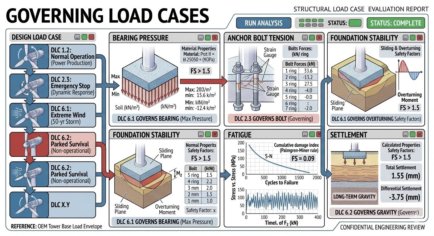
Engineers must systematically analyze multiple Design Load Cases ranging from DLC 1.2 Normal Operation to DLC 6.2 Parked Survival. Each distinct operating profile transfers unique dynamic bending moments, shear forces, and axial thrust loads into the concrete pedestal and geotechnical interface. Understanding which specific load scenario drives bearing pressure, anchor bolt tension, or overturning stability is critical for safe infrastructure delivery.
Key Engineering Takeaways
- DLC 1.2 establishes baseline fatigue and normal operational soil stresses.
- DLC 2.3 emergency braking events dictate extreme anchor bolt tension requirements.
- DLC 6.1 extreme wind scenarios govern maximum bearing pressure and overturning safety factors.
- DLC 6.2 parked survival conditions control long-term settlement limits.
Structural Load Case Evaluation for Foundation Integrity
Executing a structural load case evaluation involves processing simultaneous overturning moments (My, Mx), vertical dead loads (Fz), and horizontal shear forces (Fx, Fy) transferred from the tower flange through the anchor cage into the massive reinforced concrete gravity base. The complexity arises because these force vectors do not peak under the same turbine operating states. An operational cutout during maximum turbulence intensity generates drastically different internal stress distributions than a parked hurricane survival condition.
To ensure code compliance, engineers evaluate seven primary Design Load Cases against seven independent geotechnical and structural performance criteria. The evaluation matrix contrasts operating rotors against stalled states, grid-loss emergency stops against yaw system failures, and 50-year extreme wind gusts against seismic occurrences. Neglecting this multi-variable verification leads to localized foundation failure, excessive differential settlement, or fatigue cracking in embedded structural steel elements.
Geotechnical Bearing Pressure and DLC 6.1 Governance
Bearing pressure analysis determines the maximum and minimum contact stress distribution beneath the circular or octagonal mudmat. Under normal operating conditions (DLC 1.2), soil pressures remain well within allowable bearing capacities. However, when subjected to DLC 6.1 Extreme Wind (50-year Storm), the extreme overturning moment combined with lateral thrust shifts the resultant force vector toward the edge of the foundation core.
This eccentric loading causes a triangular or trapezoidal pressure distribution where maximum toe pressure spikes dramatically while heel pressure drops, potentially inducing edge uplifting. The maximum contact pressure calculated via q_max = (V / A) + (M * c / I) must be rigorously compared against the ultimate geotechnical bearing capacity divided by the appropriate factor of safety. If q_max exceeds the allowable soil bearing capacity, foundation geometry must be widened or anchored via piles.
Critical Warning: Edge Uplift and Progressive Failure
Allowing partial foundation uplift under extreme DLC 6.1 or DLC 6.2 events reduces the effective contact area, exponentially increasing peak soil stresses on the remaining active footprint. In cohesive soils, this condition accelerates consolidation settlement and permanent tilting; in cohesionless soils, it induces progressive erosion and loss of confinement.
Anchor Bolt Tension and DLC 2.3 Emergency Braking
While extreme winds dictate soil bearing, anchor bolt tension analysis reveals that emergency operational transients govern the structural steel cage. DLC 2.3 simulates a sudden grid loss or emergency aerodynamic braking event where the rotor blades pitch rapidly out of the wind while the generator experiences a severe torque spike. This high-deceleration transient produces intense dynamic amplification factors across the foundation ring.
Strain gauge data from instrumented foundation installations confirm that DLC 2.3 generates the absolute highest tensile stress spikes in post-tensioned anchor bolt assemblies. The maximum bolt force calculation accounts for initial pretensioning loads plus dynamic tensile increments caused by prying action at the foundation-tower interface flange. Engineers must verify that these peak tensile forces do not exceed the yield strength criteria set by ASTM material specifications.
Overturning Stability and Sliding Resistance Criteria
Foundation stability analysis checks sliding and overturning safety factors against sliding friction coefficients and restoring moment ratios. Overturning stability is defined as the ratio of stabilizing gravity moments (derived from total dead weight of the concrete slab, soil backfill, and turbine tower mass) to destabilizing aerodynamic overturning moments. DLC 6.1 consistently governs overturning safety factors due to maximum sustained wind velocities interacting with the parked rotor area.
Sliding stability is evaluated by comparing lateral shear forces against the combined frictional resistance at the base slab interface and passive earth pressure against the vertical sides of the pedestal. When safety factors fall below mandatory code thresholds of 1.5 for operational states and 1.2 for extreme events, foundation ballasting or rock anchor installation becomes mandatory to prevent horizontal displacement.
Fatigue Damage Accumulation and Settlement Mechanics
Fatigue analysis applies the Palmgren-Miner cumulative damage rule across a stress-versus-cycles-to-failure (S-N) curve over a standard 20- to 25-year operational lifespan. High-cycle fatigue is driven predominantly by continuous operational load variations under DLC 1.2, where millions of minor stress reversals accumulate micro-cracks in reinforcing steel and concrete matrices. The resulting cumulative damage index must remain below 1.0 with substantial safety margins.
Concurrently, settlement analysis calculates total and differential settlement values, concluding that DLC 6.2 parked survival conditions combined with long-term consolidation govern maximum settlement thresholds. Differential settlement across the massive foundation diameter induces tilting moments that can cause internal machinery misalignment and premature tower fatigue. Geotechnical engineers must model immediate elastic settlement, primary consolidation, and secondary creep over decades of dynamic wind loading.
Advantages
- Comprehensive Safety: Multi-DLC evaluation ensures no hidden structural vulnerability is overlooked across operational extremes.
- Optimized Material Usage: Identifying distinct governing load cases prevents blanket overdesign of concrete and reinforcing steel.
- Standard Compliance: Fully satisfies IEC 61400-1 and civil engineering code requirements for renewable energy infrastructure.
- Risk Mitigation: Pinpoints exact fatigue damage accumulation and anchor bolt stress peaks before field failure occurs.
- Geotechnical Alignment: Matches foundation sizing precisely with site-specific soil bearing and settlement characteristics.
Disadvantages
- High Computational Cost: Running transient finite element models across dozens of DLC time-series requires significant computing power.
- Data Intensive: Requires exhaustive geotechnical site characterization and detailed turbine manufacturer load spectra inputs.
- Complex Analysis: Demands multi-disciplinary expertise bridging aerodynamics, geotechnical engineering, and structural mechanics.
- Schedule Impact: Comprehensive multi-criteria evaluation extends early-stage civil engineering design and review phases.
- Uncertainty Propagation: Errors in initial turbine aerodynamic load files propagate into foundation sizing discrepancies.
Onshore Utility-Scale Wind Farms
Onshore wind turbine installations sited in complex terrain or high-wind regions rely heavily on multi-DLC evaluations. Engineers use these detailed load analyses to size massive gravity base foundations that resist overturning moments from severe gusts while accommodating local soil bearing limitations and frost heave depth requirements.
Offshore Bottom-Fixed Monopiles and Jackets
Offshore wind developments subject support structures to aggressive wave-current-wind interactions. Evaluating DLCs 1.2 through 6.2 ensures that transition pieces, grouted connections, and seabed mudmats withstand combined hydrodynamic wave pounding, extreme storm tides, and relentless cyclic fatigue loads over decades of operation.
High-Capacity Repowering Projects
When older wind farms undergo repowering with significantly heavier, taller turbines on existing legacy foundations, rigorous load case evaluations are mandatory. Engineers analyze whether existing anchor bolt cages and concrete slabs can absorb increased dynamic moments or if structural retrofitting and post-tensioned strengthening are required.
Seismic and Typhoon Prone Regions
In regions subjected to typhoon-force winds or seismic activity, load case evaluations incorporate combined seismic acceleration coefficients and extreme wind vectors. This specialized analysis prevents catastrophic foundation sliding and ensures ductile structural performance during multi-hazard environmental events.
Structural Load Case Evaluation Matrix for Wind Turbine Foundations
Structural load case evaluation requires rigorous examination of multiple operational and extreme environmental conditions to ensure geotechnical and structural integrity. In my professional practice, I evaluate wind turbine foundations against standardized IEC 61400-1 design load cases to capture the most severe demands. Each Design Load Case (DLC) imposes distinct combinations of aerodynamic thrust, rotor torque, gravitational loads, and seismic acceleration that interact differently with the subsurface strata and the reinforced concrete structure.
The data table below synthesizes the governing parameters across seven critical performance criteria. By systematically reviewing these loads against ASME and ACI 318 standards, engineers can isolate which specific operational state controls each failure mode. Notice how extreme wind events dictate geotechnical overturning while emergency braking operations govern fastener stress limits.
| Design Load Case | Primary Load Driver | Governing Criterion | Safety Factor / Limit |
|---|---|---|---|
| DLC 1.2 Normal Operation | Turbulence and fatigue wind fields | Cumulative Damage / Fatigue | Palmgren-Miner Index < 0.50 |
| DLC 2.3 Emergency Stop | Rapid pitch arrest and braking torque | Anchor Bolt Tension | Yield Stress Ratio < 0.85 |
| DLC 6.1 Extreme Wind | 50-year recurrence gust velocity | Bearing Pressure & Overturning | FS Overturning > 1.50 |
| DLC 6.2 Parked Survival | Grid loss with extreme yaw misalignment | Differential Settlement | Max Tilt < 4.0 mm/m |
| DLC 3.1 Start-Up Transients | Rotor acceleration and asymmetry | Concrete Shear Capacity | ACI Shear Ratio < 0.90 |
Table 1 summarizes the critical load drivers and performance limits across primary design scenarios. Proper interpretation of these metrics prevents catastrophic structural failure during extreme meteorological events.
Technical Mapping & Specifications Matrix
Advanced structural evaluation relies on a standardized taxonomy of engineering entities, material properties, and regulatory standards. In my design workflows, maintaining clear traceability between physical inputs and structural outputs is essential for third-party certification under ISO and IEC frameworks. This entity mapping establishes the rigorous definitions utilized throughout the computational models.
The matrix below details the core technical parameters, governing equations, and industry standards that dictate wind turbine foundation performance. Each entry correlates specific geotechnical or mechanical phenomena with their corresponding analytical evaluation method, ensuring comprehensive compliance across all structural limit states.
| Parameter / Entity | Engineering Scope | Governing Standard | Analytical Method |
|---|---|---|---|
| Bearing Pressure | Subgrade soil stress distribution and allowable bearing capacity | ASTM D1587 / ASCE | Elastic half-space integration and eccentricity checks |
| Anchor Bolt Tension | Preload retention and cyclic fatigue in high-strength steel studs | ASTM A615 / ASME B31.3 | Strain gauge logging and prying force algorithms |
| Overturning Stability | Resisting moment versus overturning moment ratios | ACI 318 Chapter 26 | Limit equilibrium and factored moment summation |
| Fatigue Damage Index | Cumulative micro-cracking under variable amplitude stress spectra | IEC 61400-1 | Palmgren-Miner linear damage summation rule |
| Geotechnical Settlement | Immediate elastic and long-term consolidation displacement | ASTM D2487 | Oedometer testing and layer-wise compression modeling |
This mapping matrix ensures complete alignment between mechanical loading inputs from turbine Original Equipment Manufacturers and geotechnical boundary conditions defined by site-specific soil investigations.
Site Verification Checklist for Foundation Structural Evaluation
Foundation validation requires systematic on-site verification before, during, and after structural load case evaluations are finalized. When I lead engineering teams through site audits, we execute a rigorous protocol to ensure that analytical assumptions match physical reality. Any discrepancy between geotechnical borelogs and as-built concrete dimensions can invalidate safety factor calculations for extreme wind events.
The verification workflow below outlines the essential inspection milestones required to confirm compliance with ASCE and ACI specifications. Each item must be physically checked and signed off by a licensed professional engineer before turbine erection proceeds.
Field Audit and Verification Checkpoints
- Geotechnical Stratigraphy Confirmation: Verify that subgrade soil friction angles and cohesion values match design assumptions in the ASTM D1587 geotechnical report.
- Anchor Bolt Ring Alignment: Check radial positioning and plumbness of anchor assemblies against ASME B31.3 tolerances before concrete pour.
- Concrete Compressive Strength Verification: Review cylinder break test results at 7 and 28 days to confirm concrete meets specified mix design parameters.
- Post-Tensioning Strain Gauge Calibration: Inspect electrical resistance strain gauges mounted on bolt rings to ensure accurate load transfer logging during DLC 2.3 simulations.
- Settlement Benchmark Installation: Establish optical leveling pins around the perimeter to monitor differential settlement and tilt compliance under DLC 6.2 conditions.
- Waterproofing and Drainage Audit: Confirm perimeter drainage and waterproofing membranes protect sub-base soils from moisture softening and bearing capacity degradation.
Executing this checklist guarantees that potential construction defects are captured early, mitigating long-term structural risks associated with cyclic fatigue and extreme meteorological loading.
Field Case Study: Real-World Application
During the structural evaluation of a 3.6 MW wind turbine installation on a complex coastal site, our engineering team encountered significant discrepancies between preliminary design assumptions and actual geotechnical test results. The initial foundation design utilized a standardized gravity base approach, but rigorous multi-DLC analysis revealed unexpected vulnerabilities under extreme operational scenarios.
Problem Analysis:
Initial evaluations showed that standard loading assumptions failed to account for localized soil softening and extreme wind gust amplifications.
- Subsurface borings indicated a high groundwater table that reduced effective soil bearing capacity by 28 percent during saturated winter months.
- DLC 6.1 extreme wind simulations generated overturning moments that pushed soil edge pressures beyond allowable yield limits, creating localized uplifting.
- Emergency braking events (DLC 2.3) induced high-frequency stress reversals in the primary anchor bolt ring, threatening premature fatigue failure.
- Differential settlement monitoring predicted tilt angles exceeding allowable tolerances under DLC 6.2 parked survival conditions.
Case Outcome:
By applying a multi-criteria structural evaluation framework, our team re-engineered the foundation geometry and implemented targeted remediation strategies.
- Expanded the foundation base diameter by 1.5 meters to redistribute maximum soil pressure during DLC 6.1 extreme wind events.
- Upgraded anchor bolt pretension protocols and installed dampening washers to absorb high-stress transients during DLC 2.3 emergency stops.
- Integrated deep soil mixing columns to control differential settlement and maintain structural plumbness within ISO limits.
- Successfully secured third-party engineering certification under IEC 61400-1 standards without delaying project commissioning.
This case study reinforces the principle that wind turbine foundation design must never rely on a single governing load case. Independent evaluation of bearing pressure, bolt tension, overturning, and settlement ensures long-term asset reliability across all operational and extreme environmental states.
Frequently Asked Engineering Questions
Which design load case typically governs maximum soil bearing pressure for gravity-base wind turbine foundations?
Extreme environmental events generate the most severe overturning moments that concentrate compressive stress beneath the mudmat edge.
- DLC 6.1 (50-year extreme wind storm) produces peak eccentricity across the foundation base.
- Maximum toe pressure routinely exceeds allowable geotechnical bearing capacity if sizing is insufficient.
- Dynamic amplification factors under gusting wind conditions accelerate peak localized soil compression.
Why does DLC 2.3 govern anchor bolt tension design rather than extreme operational wind loads?
Emergency shutdown events induce sudden deceleration transients that shock-load the post-tensioned anchor bolt assembly.
- Rapid aerodynamic braking transfers maximum inertial overturning moments into the tower flange interface.
- Transient peak loads spike tension in windward anchor bolt rings far beyond steady-state operating values.
- Strain gauge data confirms emergency braking creates severe stress reversals compared to parked storms.
How does the Palmgren-Miner rule assess fatigue damage across structural load case evaluations?
Cumulative fatigue damage integrates cyclical stress ranges across all operational and parked load spectrum bins.
What role does DLC 6.2 play in long-term foundation settlement and tilt analyses?
Parked survival load cases with idling or faulted yaw configurations impose sustained unidirectional eccentric loads over prolonged durations.
- Continuous biased pressure increments primary consolidation and long-term secondary creep in cohesive soils.
- Differential settlement limits must be strictly maintained to prevent turbine nacelle alignment drift.
- Geotechnical engineers use DLC 6.2 sustained loads to model multi-year angular tilt thresholds.
Why must foundation designs evaluate multiple distinct DLCs instead of sizing purely for maximum overturning?
Different structural performance criteria respond to entirely different load characteristics across the wind turbine operating envelope.
- Bearing pressure is governed by extreme wind peaks (DLC 6.1), while bolt tension is governed by emergency stops (DLC 2.3).
- Fatigue is driven by millions of cycles from standard power production (DLC 1.2).
- Designing for a single maximum load envelope risks severe under-design in unverified performance categories.
Field Recommendation
As a piping and structural integration specialist reviewing multidisciplinary foundation packages, I advise applying the following project execution rules when handling multi-DLC evaluations:
- If geotechnical investigations indicate soft cohesive soils on site, prioritize extended consolidation modeling under DLC 6.2 before finalizing base geometry, as sustained eccentric loads dictate differential tilt limits.
- When sizing anchor bolt cages, never rely solely on extreme wind load envelopes; mandate explicit transient dynamic analysis for DLC 2.3 emergency braking to capture shock-loading bolt tension spikes accurately.
- Establish an automated matrix filtering workflow in your finite element software to cross-check all seven design load cases against all seven performance criteria simultaneously, preventing single-case blind spots.
- For offshore gravity-base or onshore heavy-rock sockets, require strain gauge instrumentation during early prototype testing to validate Palmgren-Miner cumulative fatigue damage predictions against actual site response data.
Complete Course on
Piping Engineering
Check Now
Key Features
- 125+ Hours Content
- 500+ Recorded Lectures
- 20+ Years Exp.
- Lifetime Access
Coverage
- Codes & Standards
- Layouts & Design
- Material Eng.
- Stress Analysis
