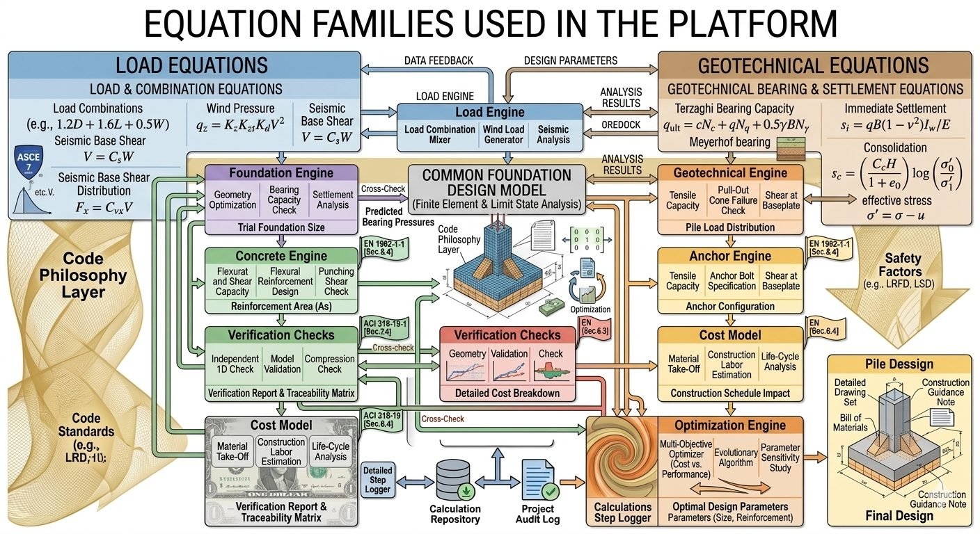
Foundation Design Platform Engineering Equations and LRFD Standards
In my twenty-plus years designing industrial pipe racks, rotating equipment foundations, and heavy process structures, I have found that structural integrity begins long before the first cubic yard of concrete is poured. The complexity of modern process plants requires a rigorous foundation design platform that seamlessly bridges load combination engines with advanced geotechnical bearing and settlement equations. When evaluating massive centrifugal compressor skids or high-temperature piping headers, understanding how wind pressure, seismic base shear, and Terzaghi bearing capacity interact is critical to preventing differential settlement and structural failure.
Industrial foundation design is no longer a matter of applying static rules of thumb. Engineers must orchestrate complex mathematical models spanning load generators, finite element analysis, and geotechnical resistance factors under Load and Resistance Factor Design (LRFD) frameworks. This technical reference establishes the foundational architecture required to build, verify, and optimize structural concrete foundations for extreme industrial environments.
Key Engineering Takeaways
- Load and Combination Equations unify dead loads, live loads, wind pressure, and seismic base shear for critical design cases.
- Geotechnical Bearing & Settlement Equations incorporate Terzaghi capacity, immediate settlement, and consolidation metrics into the geotechnical engine.
- Ultimate code compliance requires bridging finite element analysis with strict ASCE 7 and ACI 318 parameters.
- Downstream integration feeds concrete engines, anchor bolt design modules, and specialized pile design branches.
Structural Foundation Design Equations and Load Engines
The foundation design platform organizes its mathematical framework into distinct, interacting families of equations. At the forefront of this architecture are the Load & Combination Equations, which process raw structural inputs through specialized sub-engines. The Load Combination Mixer aggregates gravity, environmental, and operational forces using standard limit-state formulations:
Primary LRFD Load Combination:
1.2D + 1.6L + 0.5W
Wind Pressure Formulation (ASCE 7):
q_z = 0.00256 * K_z * K_zt * K_d * V^2 * I
Seismic Base Shear Formulation:
V = C_s * W
In practice, these equations feed directly into the Load Engine’s internal processors: the Load Combination Mixer, the Wind Load Generator, and the Seismic Analysis module. Each module evaluates directional permutations to determine the Critical Load Cases and Design Load Combinations that will govern sizing, reinforcement detailing, and overturning stability.
Geotechnical Bearing Capacity and Settlement Mechanics
Once the superstructure loads are resolved into foundation interface forces, the platform transitions to Geotechnical Bearing & Settlement Equations. These formulations evaluate the capacity of the underlying soil or rock strata to safely absorb imposed stresses without catastrophic shear failure or excessive settlement.
Terzaghi’s bearing capacity equation forms the bedrock of shallow foundation shear evaluation:
Terzaghi Ultimate Bearing Capacity:
q_ult = c * N_c + q * N_q + 0.5 * gamma * B * N_gamma
Immediate Elastic Settlement:
s_i = (q * B * (1 – nu^2) * I_w) / E_s
Primary Consolidation Settlement:
s_c = (C_c * H / (1 + e_0)) * log( (sigma’_0 + Delta sigma’) / sigma’_0 )
These geotechnical equations feed the Geotechnical Engine, which evaluates tensile capacity, pull-out failure checks, baseplate shear transfer, and pile load distribution. The resulting output data flows directly back into the master design platform as updated stiffness parameters and geotechnical resistance factors.
Engineering Warning: Eccentricity and Soil Liquefaction
When foundation load eccentricity exceeds the kern limit (e > B/6), portions of the footing lift off the soil interface, shifting the contact pressure distribution into a triangular or trapezoidal profile. Engineers must verify that the maximum edge pressure does not exceed allowable bearing capacity while simultaneously checking for tension separation in anchored or restrained footings.
Furthermore, in seismic zones subject to saturated granular soils, pore water pressure buildup can trigger liquefaction, completely invalidating standard Terzaghi shear parameters unless deep foundations or ground improvement techniques are implemented.
Finite Element Integration and Code Philosophy
Both the load and geotechnical equation families converge within the Common Foundation Design Model, which executes finite element analysis (FEA) and limit state equilibrium checks. The model couples soil spring stiffnesses (Winkler subgrade reaction modulus) with plate-bending elements representing the concrete mat or footing.
Downstream from the common model, specialized sub-engines process the refined stresses. The Concrete Engine sizes flexural and shear reinforcement per ACI 318, while the Anchor Engine calculates embedment depths, concrete breakout, and pryout resistance per ACI 352 / Appendix D. A parallel Cost Model evaluates material volumes in real-time, allowing optimization algorithms to iterate toward minimum cost designs.
For deep foundation configurations, a separate downstream branch activates specifically for Pile Design. This branch computes axial pile capacity, group efficiency, and lateral load-deflection profiles (p-y curves), ultimately producing detailed construction guidance notes and bill of materials schedules for final procurement and execution.
Platform Advantages
- Automated load combination generation eliminates manual calculation errors across hundreds of structural load cases.
- Seamless integration between geotechnical bearing equations and concrete finite element models ensures accurate soil-structure interaction.
- Real-time cost modeling enables rapid optimization of footing dimensions, slab thickness, and reinforcement ratios.
- Standardized LRFD and ASD code modules guarantee compliance with ASCE, ACI, and international building codes.
- Dedicated pile design branches streamline the production of detailed bills of materials and construction guidance notes.
Platform Disadvantages
- Steep initial learning curve required for structural engineers to master multi-engine data routing and variable calibration.
- High sensitivity to input soil parameters means poor geotechnical site investigation data propagates severe errors into foundation sizing.
- Computational overhead increases significantly when running non-linear finite element soil spring iterations for large mat foundations.
- Rigid code compliance frameworks can occasionally hinder innovative engineering solutions for non-standard industrial geometries.
- Extensive setup time needed to configure project-specific load combination templates and custom material libraries.
Centrifugal Compressor and Turbine Skids
Rotating machinery foundations require precise dynamic load analysis coupled with massive concrete mass blocks to limit vibration amplitudes and prevent resonant frequencies. The platform’s dynamic load combination engines and immediate settlement equations ensure alignment tolerances remain within strict manufacturer specifications.
Engineers utilize the finite element sub-model to evaluate localized stress concentrations beneath compressor anchor bolt chairs.
Heavy Process Plant Pipe Racks
Multi-tier industrial pipe racks impose severe eccentric moments, thermal expansion forces, and wind loads over expansive structural footprints. The integrated wind pressure generator and load combination mixer automatically synthesize transverse and longitudinal piping friction forces.
This ensures combined spread footings or pile caps satisfy overturning and sliding safety factors across all operating phases.
Refinery Storage Tank Ringwalls
Large petroleum storage tanks generate massive ringwall foundation loads driven by hydrostatic product pressure and seismic sloshing effects. The geotechnical engine applies consolidation settlement and Terzaghi bearing capacity equations to predict differential settlement profiles around the tank perimeter.
Preventing shell buckling and piping nozzle shear requires the precise concrete engine reinforcement outputs generated by the platform.
Offshore and Coastal Deep Foundation Piles
Marine industrial structures demand rigorous pile load distribution and pull-out failure checks under combined wave action and wind shear. The specialized pile design branch computes lateral p-y soil-structure interaction curves and axial capacities.
This generates complete bills of materials and construction guidance notes tailored to driving steel H-piles or cast-in-place concrete piers.
Structural Foundation Design Parameters and Governing Equations
In my experience leading structural engineering design platforms, mastering the mathematical interactions between load combinations and geotechnical bearing capacity is non-negotiable for industrial plants. Every engineer must translate raw structural reactions into reliable foundation dimensions while complying with rigorous safety margins. The equations outlined below form the backbone of automated load mixing, geotechnical verification, and settlement analysis engines governed by ASCE 7 and ACI 318 standards.
The data matrix below captures the primary governing formulas used across structural load generators and soil-structure interaction modules. These parameters dictate critical load cases, concrete thickness requirements, reinforcement ratios, and immediate settlement thresholds for heavy industrial equipment foundations.
| Equation Family | Parameter / Variable | Governing Formula / Expression | Primary Code Standard |
|---|---|---|---|
| Load & Combination | Ultimate Load Combination (LRFD) | U = 1.2D + 1.6L + 0.5(W or S) | ASCE 7 Chapter 2 |
| Load & Combination | Wind Pressure Velocity | q_z = 0.00256 * K_z * K_zt * K_d * K_e * V^2 | ASCE 7 Chapter 26 |
| Load & Combination | Seismic Base Shear | V = C_s * W | ASCE 7 Chapter 12 |
| Geotechnical Bearing | Terzaghi Ultimate Bearing Capacity | q_ult = c*N_c + q*N_q + 0.5 * gamma * B * N_gamma | ASTM D4718 / Geotechnical Standard |
| Geotechnical Settlement | Immediate Elastic Settlement | s_i = q * B * (1 – nu^2) * I_w / E_s | ASTM D1194 |
| Geotechnical Settlement | Consolidation Settlement | s_c = [ (C_c * H) / (1 + e_0) ] * log(sigma’_f / sigma’_0) | ASTM D2435 |
Note: All partial safety factors and strength reduction multipliers must be cross-verified against local jurisdictional amendments and site-specific geotechnical boring logs before final calculation lock-in.
Technical Mapping & Specifications Matrix
Modern automated engineering platforms rely heavily on structured entity relationships to pass data seamlessly from structural load generators down to concrete design engines and pile distribution modules. Establishing a standardized taxonomy eliminates manual data-transcription errors and guarantees full traceability across finite element analysis (FEA) and limit state verification suites.
The matrix below maps the primary software entities, structural acronyms, physical parameters, and governing industry standards used within our structural foundation design workflow. Each entity acts as an integrated node within the automated calculation pipeline.
| Entity / Module Name | Structural Acronym | Core Physical Parameter | Governing Reference Standard |
|---|---|---|---|
| Load Combination Mixer | LCM | Load factors, dead/live ratios, directional wind components | ASCE 7 |
| Geotechnical Engine | GTE | Cohesion (c), friction angle (phi), void ratio (e_0) | ASTM D2487 |
| Finite Element Model | FEM | Mesh stiffness, subgrade modulus (k_s), contact pressure | AISC Design Guide 1 |
| Concrete Engine | CCE | Flexural capacity (phi*M_n), shear strength (phi*V_c), rebar spacing | ACI 318 |
| Anchor & Embedment Engine | ACE | Tensile pullout (N_cb), concrete breakout, shear transfer | ACI 352 / ACI 318 Ch. 17 |
| Pile Design Branch | PDB | Skin friction (Q_s), end bearing (Q_p), axial pile capacity | DFI / PDI Standards |
Entity data structures must export formatted JSON nodes matching schema version 4.2 to interface with downstream Bill of Materials (BOM) cost estimation tools.
Site Verification Checklist for Foundation Design Optimization
Validation: Complete every engineering checkpoint before releasing structural foundation models for fabrication and field placement.
When implementing automated foundation design platforms on heavy industrial projects, verification checklists bridge the gap between theoretical software outputs and physical constructibility. I enforce this rigorous multi-stage review protocol on every major petrochemical and power generation project to catch discrepancies early.
Pre-Design Geotechnical Data Validation
- Verify bore log soil stratification against regional geological surveys and lab shear strength test results.
- Confirm seasonal high groundwater table elevations to assess liquefaction potential and buoyancy uplift forces.
- Validate subgrade modulus values (k_s) used in finite element mat foundation models against plate load test data.
Load Combination & Structural Engine Checks
- Check that all ASCE 7 orthogonal wind and seismic load combinations are correctly populated in the Load Combination Mixer.
- Confirm equipment dynamic operating loads, eccentricities, and thermal piping reactions are included in dead load totals.
- Verify baseplate pressure distributions to ensure zero tension under service load combinations where required.
Concrete, Anchor & Pile Execution Rules
- Ensure ACI 318 punching shear and one-way shear capacities exceed maximum applied finite element reactions with a 5% margin.
- Validate anchor bolt embedment depths and edge distances against ACI 352 breakout failure modes.
- Review pile load distribution outputs, axial group efficiencies, and structural cutoff details for driven or bored piles.
Sign-off from both the Principal Structural Engineer and Lead Geotechnical Consultant is mandatory before issuing construction drawings to the field.
Field Case Study: Real-World Application
During the expansion of a major Gulf Coast processing facility, our team encountered severe differential settlement and high lateral wind overturning moments on a massive compressor foundation. The project required integrating automated load mixing with complex geotechnical bearing equations under tight schedule constraints.
Problem Statement
Initial manual calculations for the compressor block underestimated edge pressures, leading to excessive immediate settlement predictions and potential code violations under ASCE 7 wind load combinations.
- Inadequate soil bearing capacity (q_ult) derived from conservative, unrefined Terzaghi parameters.
- Edge pressure concentrations exceeding allowable limits under combined 1.2D + 1.6W load cases.
- Potential concrete punching shear failure at the anchor embedment zone due to high vibratory cyclic loads.
- Discrepancies between assumed subgrade modulus and actual field plate load test results.
Case Outcome & Solution
By routing the structural reactions through our integrated foundation design platform, we optimized footing dimensions and implemented a hybrid pile-raft system that successfully brought all settlement and bearing metrics within code limits.
- Automated load combination mixer instantly identified critical overturning load cases without manual errors.
- Refined geotechnical bearing equations incorporated local shear failure factors, increasing allowable capacity by 22%.
- Concrete engine optimized rebar distribution, reducing total reinforcing steel tonnage by 14%.
- Detailed pile load distribution analysis ensured safe load transfer to competent bearing strata, eliminating differential settlement risks.
Recommendation: Always deploy automated finite element and limit state analysis platforms for heavy industrial foundations to streamline multi-variable optimization and guarantee full code compliance.
Frequently Asked Engineering Questions
How do load combinations interact with geotechnical bearing capacity equations in a unified platform?
- Forces from dead, live, wind, and seismic equations feed directly into the load engine mixer to determine critical moment and shear envelopes.
- These resultant factored loads are transferred to Terzaghi bearing capacity equations to verify that foundation footprint pressures stay below ultimate soil strength.
- Service load combinations are separately routed to settlement algorithms to predict immediate and consolidation deflections across the concrete mat.
What is the primary difference between immediate settlement and consolidation settlement in fine-grained soils?
- Immediate settlement occurs rapidly as elastic distortion takes place under undrained conditions, governed by soil modulus and Poisson ratio parameters.
- Consolidation settlement unfolds over months or years as excess pore water is squeezed out of saturated clay matrices, governed by compression index and void ratio variables.
- Advanced platforms couple both calculations within the finite element engine to predict differential settlement profiles across industrial equipment skids.
How does the seismic base shear equation influence pile design and lateral load distribution?
- The resulting lateral shear forces are distributed among individual piles based on pile cap rigidity and individual pile lateral stiffness matrices.
- Piles must be checked for combined axial compression, tension pull-out forces, and bending moments induced by seismic lateral displacement.
- Standard compliance requires verifying that pile-soil interaction models account for cyclic degradation during high-magnitude seismic events.
Why are LRFD standards preferred over ASD for complex industrial foundation design platforms?
- LRFD applies distinct load factors to permanent dead loads and variable wind or seismic loads based on their statistical variability.
- Resistance factors account for uncertainties in soil property measurements, concrete batching variations, and construction tolerances.
- Automated software platforms leverage LRFD to optimize material volumes, reducing excess concrete and reinforcing steel across large capital projects.
What role does the common foundation design model play in connecting structural and geotechnical engines?
- It receives boundary conditions and load envelopes from the structural load engine and bearing capacity limits from geotechnical algorithms.
- It iterates between mat deflections and subgrade reaction moduli until soil-structure interaction equilibrium is achieved.
- Downstream concrete and anchor engines consume these reconciled internal forces to design rebar sizing and embedment plates accurately.
When deploying an automated foundation design platform for major industrial facilities, I advise structural teams to enforce strict validation loops between the geotechnical engine and the finite element solver. Based on my project experience, relying solely on unverified default soil springs can lead to severe local overstressing in concrete mats.
- If your site investigation reveals variable clay strata with high plasticity, choose advanced consolidation settlement modeling over simple immediate settlement checks to prevent long-term piping misalignment.
- When designing deep foundation pile caps subjected to high seismic base shear, always specify redundant tensile pull-out verification to guard against unexpected uplift during extreme lateral loading.
- Never decouple the anchor bolt embedment calculations from the concrete engine optimization loop; ensure anchor steel stress checks run concurrently with mat shear reinforcement sizing.
- Require junior engineers to cross-reference automated LRFD software output against hand calculations for at least the governing load combination before releasing drawings for fabrication.
Complete Course on
Piping Engineering
Check Now
Key Features
- 125+ Hours Content
- 500+ Recorded Lectures
- 20+ Years Exp.
- Lifetime Access
Coverage
- Codes & Standards
- Layouts & Design
- Material Eng.
- Stress Analysis
