
Street Elbow vs Piping Elbow: Key Differences and Engineering Guide
In my 20 years of managing piping stress analyses and field installations, I have seen minor fitting choices make or break a project. One of the most common debates among junior designers and field technicians involves the application of a street elbow versus a standard piping elbow. While they might look interchangeable on a simple schematic, their structural behavior, flow characteristics, and pressure ratings differ significantly.
When you are designing a tight manifold for a chemical skid or laying out a utility water line, every millimeter of clearance matters. However, substituting a standard elbow with a street elbow without analyzing the mechanical limits can lead to premature fatigue failures, especially in cyclic or high-vibration services. Let us dive deep into the engineering realities of these two critical components.
Key Engineering Takeaways
- Thread Configuration: Standard elbows have female-to-female threads, whereas street elbows feature one male and one female thread.
- Space Optimization: Street elbows eliminate the need for an intermediate close nipple, reducing the overall fitting envelope by up to 15 percent.
- Stress Concentrations: The male neck of a street elbow acts as a cantilever, making it highly susceptible to bending moments and fatigue under cyclic loads.
- Code Compliance: ASME B31.3 and ASME B31.1 place strict limitations on the use of street elbows in severe cyclic or hazardous fluid services.
Complete Course on
Piping Engineering
Check Now
Key Features
- 125+ Hours Content
- 500+ Recorded Lectures
- 20+ Years Exp.
- Lifetime Access
Coverage
- Codes & Standards
- Layouts & Design
- Material Eng.
- Stress Analysis
Why Choose Street Elbow vs Piping Elbow Fittings?
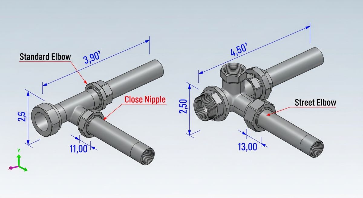
To understand the mechanical differences, we must first look at the physical geometry. A standard piping elbow (often governed by ASME B16.11 for forged fittings) has female NPT threads on both runs. To connect this elbow to another female-threaded component, you must thread a short piece of pipe, known as a close nipple, into the elbow.
A street elbow, on the other hand, features an integrated male thread on one end and a female thread on the other. This design allows you to thread the male end directly into a female port of a valve, manifold, or vessel, completely bypassing the close nipple.
The Space-Saving Mathematics
Let us calculate the physical envelope reduction when using a 1-inch NPT Class 3000 threaded assembly.
- Standard Assembly: A standard 1-inch elbow has a center-to-end dimension (A) of 1.50 inches (38.1 mm). A close nipple has a length of 1.50 inches. When assembled, the thread engagement length (L_e) for 1-inch NPT is approximately 0.68 inches. The total combined length of the elbow and nipple assembly is:
Total Length = Center-to-End + Nipple Length – Thread Engagement
Total Length = 1.50 in + 1.50 in – 0.68 in = 2.32 inches (58.9 mm)
- Street Elbow Assembly: A 1-inch Class 3000 street elbow has a center-to-female-end dimension of 1.50 inches and a center-to-male-end dimension of 2.00 inches (50.8 mm). Because the male thread is integrated, no nipple is required. The total length from the center of the elbow to the face of the receiving female fitting is simply the male center-to-end dimension:
Total Length = 2.00 inches (50.8 mm)
By choosing a street elbow, you save 0.32 inches (8.1 mm) of linear space. In a compact hydraulic skid with dozens of connections, this cumulative space saving is massive. More importantly, you eliminate one entire threaded joint, reducing your potential leak paths by 50 percent for that specific turn.
Stress Concentration and Mechanical Vulnerability
Despite the space savings, street elbows introduce a structural vulnerability that I always caution my engineering team about. The male threaded neck of a street elbow has a smaller cross-sectional area than the heavy-walled body of a standard female elbow.
When a piping system undergoes thermal expansion or mechanical vibration, bending moments are generated. In a standard elbow assembly, these forces are distributed across the thick fitting wall and the heavy pipe nipple. In a street elbow, the bending stress concentrates directly at the root of the first exposed male thread on the fitting neck. This notch effect, combined with the cantilevered load, significantly reduces the fatigue life of the joint.
Do not use street elbows in piping systems subject to severe cyclic thermal conditions, water hammer, or high-frequency mechanical vibrations (such as reciprocating pump discharge lines). Under ASME B31.3 Section 306.1.2, threaded joints that are subject to bending or fatigue must be evaluated with extreme care, and street elbows are frequently restricted from these services due to their high stress concentration factors.
The following data table compares the dimensions and pressure ratings of forged carbon steel street elbows and standard 90-degree elbows in accordance with ASME B16.11 (Class 3000).
| Nominal Pipe Size (NPS) | Std Elbow Center-to-End (in) | Street Elbow Female Center-to-End (in) | Street Elbow Male Center-to-End (in) | Class 3000 Cold Working Pressure (PSI) |
|---|---|---|---|---|
| 1/4″ | 0.97 | 0.97 | 1.25 | 3000 |
| 1/2″ | 1.31 | 1.31 | 1.62 | 3000 |
| 3/4″ | 1.50 | 1.50 | 1.88 | 3000 |
| 1″ | 1.75 | 1.75 | 2.25 | 3000 |
| 1-1/2″ | 2.38 | 2.38 | 2.88 | 3000 |
| 2″ | 2.50 | 2.50 | 3.25 | 3000 |
| Design Parameter | Street Elbow | Standard Piping Elbow | Governing Standard |
|---|---|---|---|
| Thread Gender | Male x Female (NPT or BSPT) | Female x Female (NPT or BSPT) | ASME B1.20.1 |
| Leak Path Count | Single threaded joint per turn | Two threaded joints (requires nipple) | Industry Best Practice |
| Fatigue Resistance | Low (high stress concentration at male neck) | High (uniform wall thickness) | ASME B31.3 Chapter II |
| Flow Resistance (K-Factor) | Slightly higher due to internal diameter transition | Lower (consistent internal bore) | Crane Technical Paper 410 |
| Common Materials | Forged Steel, Brass, Cast Iron, Stainless Steel | Forged Steel, Cast Iron, Ductile Iron, PVC | ASTM A105 / ASTM A182 |
Verifying Threaded Fittings on Project Sites
During field audits, I often find that installation crews treat street elbows like standard fittings, ignoring the torque limits of the male neck. Use this checklist on your job site to prevent mechanical failures during hydrotesting or operation.
Field Inspection Protocol
-
Verify Pressure Rating: Ensure the fitting stamp matches the piping class (e.g., Class 3000 or Class 6000 for forged steel) and is not a low-pressure cast iron fitting mistakenly used in process piping. -
Inspect Male Thread Root: Check the transition zone between the male threads and the hexagonal body of the street elbow for micro-cracks, casting defects, or deep tool marks. -
Control Torque Application: Ensure pipe wrenches are placed on the fitting body, not on the male neck, to prevent torsional deformation during tightening. -
Thread Sealant Compatibility: Confirm that the selected thread sealant (PTFE tape or anaerobic compound) is chemically compatible with the process fluid and temperature limits. -
Check Alignment: Verify that the connected piping run is perfectly aligned. Forcing an out-of-alignment pipe into a street elbow introduces severe static bending stresses on the male neck.
Analyzing Street Elbow vs Piping Elbow Stress Profiles
To illustrate the real-world consequences of fitting selection, let us look at a case study from a project I audited in 2018. The incident highlights why theoretical stress profiles must dictate field installation practices.
A chemical processing plant experienced repeated hydrocarbon leaks on a 1.5-inch lube oil return line connected to a high-speed centrifugal compressor. The original contractor had used a Class 3000 carbon steel street elbow to connect the line directly to the compressor housing, aiming to clear a structural steel beam located just inches away. Within 14 months of operation, the joint failed at the first thread of the male run, causing an unscheduled plant shutdown and significant environmental cleanup costs.
I led the Root Cause Analysis (RCA) team. Finite Element Analysis (FEA) revealed that high-frequency mechanical vibration from the compressor induced a localized bending stress of 24,000 PSI at the root of the street elbow’s male thread, exceeding the fatigue limit of the material. We modified the piping layout by shifting the run 2 inches to clear the structural beam. This allowed us to replace the street elbow with a standard Class 3000 forged elbow and a seamless Schedule 80 pipe nipple. The redesigned joint reduced the localized stress to 8,500 PSI. The system has now operated for over eight years without a single leak.
This case study proves that while street elbows are highly convenient for tight spaces, they should never be used as a shortcut to bypass proper piping layout design. If a space constraint forces you to use a street elbow, you must perform a rigorous stress analysis to ensure the mechanical loads do not exceed the fatigue threshold of the threaded neck.
Frequently Asked Engineering Questions
What is the primary structural difference between a street elbow and a standard elbow?
Can I use a street elbow in high-pressure steam service?
How much space does a street elbow actually save?
Why are street elbows more prone to fatigue failure?
What standards govern the dimensions of street elbows?
