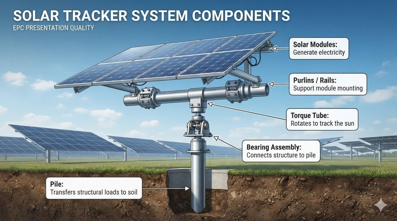
Optimizing the Solar Tracker System for Industrial Energy Yield
In my two decades of experience within industrial piping and structural design, I have observed that the efficiency of a utility-scale solar farm rests entirely on the mechanical integrity of its mounting hardware. A solar tracker system is not merely a rack; it is a dynamic, rotating machine that must withstand decades of wind loads, thermal expansion, and soil-structure interaction.
Understanding the five core components—modules, purlins, torque tubes, bearings, and piles—is the first step toward ensuring project longevity. When these elements are correctly specified and aligned, the system achieves optimal energy yield while minimizing maintenance overhead. I have seen too many projects fail due to improper bearing selection or inadequate pile depth, which is why I emphasize a rigorous, component-based approach to structural design.
Key Takeaways for Engineers
- The torque tube acts as the primary structural spine for rotational movement.
- Bearing assemblies must be rated for high-cycle fatigue and environmental exposure.
- Pile depth is determined by geotechnical soil reports and lateral load resistance.
- Purlins provide the critical interface between the module frame and the tracker spine.
Engineering the Solar Tracker System for Structural Integrity
Structural performance: The capacity of a solar tracker system to maintain geometric stability under combined static and dynamic loads, adhering to ASCE 7 wind load standards.
Designing a robust solar tracker system requires a deep dive into the load path from the photovoltaic module down to the foundation. The torque tube is the most critical structural member, often designed as a hollow structural section (HSS) to provide high torsional rigidity. When calculating the required section modulus, I always account for the maximum wind-induced torsional moment, which can be significant during extreme weather events.
The bearing assembly serves as the pivot point, transferring the torque tube’s rotation to the fixed pile. In my experience, selecting a bearing with high radial and axial load capacity is non-negotiable. These components must be protected against ingress of dust and moisture, as failure here leads to catastrophic system downtime. I recommend referencing ISO 76 for static load ratings when evaluating bearing life cycles.
Design Limitation Warning
Never exceed the allowable deflection limits for purlins, as excessive bending can induce micro-cracking in the silicon wafers of the modules. Always verify the span-to-depth ratio against manufacturer specifications and local building codes.
The pile foundation is the final link in the chain. Whether using driven piles or helical anchors, the design must satisfy the lateral load requirements defined by the soil’s shear strength. I perform a p-y curve analysis to model the soil-pile interaction, ensuring that the tracker system remains stable even under peak wind gusts. The connection between the pile and the bearing must be rigid enough to prevent vibration-induced fatigue, which is a common failure mode in high-wind regions.
Finally, the purlins and rails must be designed for ease of installation while maintaining structural continuity. I prefer using cold-formed steel sections that offer high strength-to-weight ratios. By integrating these five components into a cohesive structural model, we ensure that the solar tracker system operates within its design envelope for the duration of its 25-year service life.
System performance trade-offs: The balance between increased energy production through active tracking and the added complexity of mechanical maintenance requirements.
Advantages
- Significant increase in daily energy yield compared to fixed-tilt systems.
- Optimized angle of incidence throughout the day reduces reflection losses.
- Improved land-use efficiency by maximizing power density per acre.
- Active tracking allows for stow positions during high-wind events.
- Better performance in early morning and late afternoon hours.
Disadvantages
- Higher initial capital expenditure due to mechanical components.
- Increased maintenance requirements for bearings and drive motors.
- Potential for mechanical failure in harsh, corrosive environments.
- Complex control systems require specialized monitoring software.
- Greater sensitivity to uneven terrain and geotechnical variability.
Industrial deployment scenarios: The strategic implementation of solar tracker systems across diverse environments to optimize power generation and structural reliability.
Utility-Scale Solar Farms
In large-scale desert installations, trackers are the standard for maximizing ROI. The high direct normal irradiance makes the mechanical complexity of the torque tube and bearing assembly highly cost-effective over the project lifespan.
Brownfield Redevelopment
Converting former industrial sites into solar parks requires robust pile foundations that can penetrate varied soil conditions. The modular nature of the tracker components allows for flexible layout adjustments to avoid subsurface obstructions.
Agricultural Dual-Use Projects
Agrivoltaics often utilize elevated tracker systems to allow for machinery clearance beneath the modules. This requires specialized pile designs to maintain structural stability while providing the necessary height for farming operations.
In my experience, the structural integrity of a solar tracker system relies on precise load distribution across the five primary components. Engineers must account for static dead loads from the modules and dynamic wind loads that exert significant torsional force on the torque tube and bearing assemblies. The following table outlines the typical design criteria and performance metrics I utilize when evaluating these systems under ASCE 7-22 standards for wind and seismic exposure.
| Component | Primary Load Type | Design Standard | Failure Mode |
|---|---|---|---|
| Solar Modules | Gravity/Snow | IEC 61215 | Micro-cracking |
| Purlins/Rails | Bending/Shear | AISI S100 | Local Buckling |
| Torque Tube | Torsion/Vibration | AISC 360 | Galloping/Flutter |
| Bearing Assembly | Rotational/Axial | ISO 281 | Seizure/Wear |
| Pile Foundation | Lateral/Uplift | ASTM D3689 | Soil Liquefaction |
These values represent baseline engineering requirements. When designing for high-wind regions, I often increase the safety factors for the torque tube and bearing assembly to mitigate the risk of aeroelastic instability, which remains the most common cause of structural failure in large-scale utility projects.
The following matrix maps the physical entities of a solar tracker system to their respective engineering specifications and material properties. Understanding these relationships is necessary for maintaining the structural health of the solar tracker system throughout its 25-year operational lifespan. Each component is evaluated based on its material composition, connection type, and primary function within the kinematic chain.
| Entity | Material Class | Connection Method | Standard Ref |
|---|---|---|---|
| Modules | Silicon/Glass | Clamping | IEC 61730 |
| Purlins | Galvanized Steel | Bolted | ASTM A653 |
| Torque Tube | Structural Steel | Welded/Bolted | AISC 360 |
| Bearing | UHMWPE/Steel | Press-fit | ISO 1461 |
| Pile | Carbon Steel | Driven/Screw | ASTM A500 |
By standardizing these specifications, we ensure that the solar tracker system maintains consistent performance across varying soil conditions and climate zones. Proper material selection, particularly regarding corrosion resistance for piles and bearing lubrication, is the primary driver of long-term project bankability.
Verification: A comprehensive site verification process ensures the solar tracker system meets all structural design tolerances before commissioning. In my experience, failing to verify pile verticality or torque tube alignment during the initial installation phase leads to premature bearing failure and increased motor load, which can significantly reduce the system’s energy yield over time.
- [ ] Pile Verticality: Verify that all driven piles are within 1 degree of verticality as per ASTM D3689 to prevent binding in the bearing assembly.
- [ ] Torque Tube Alignment: Ensure the torque tube is laser-leveled across the entire row to minimize torsional stress on the drive motor.
- [ ] Bearing Lubrication: Confirm that all bearing assemblies are properly greased and free of debris before the final torque tube installation.
- [ ] Purlin Torque Specs: Validate that all rail-to-tube bolts are torqued to the manufacturer’s specified value using a calibrated torque wrench.
- [ ] Module Clamping: Check that module clamps are tightened to the required pressure to prevent vibration-induced micro-cracking of the silicon cells.
Following this checklist is not merely a quality control exercise; it is a fundamental requirement for maintaining the structural warranty of the solar tracker system. I recommend documenting every step with photographic evidence and torque logs to satisfy the requirements of the project’s independent engineer and insurance underwriters.
Problem: Premature Bearing Seizure in High-Wind Environment
A 50MW utility-scale project experienced widespread bearing failure within the first 18 months of operation due to excessive torsional vibration.
- Inadequate pile depth leading to foundation instability.
- Misalignment of the torque tube causing uneven load distribution.
- High-frequency aeroelastic flutter during wind events.
- Lack of periodic lubrication maintenance on the bearing assembly.
Outcome: Structural Remediation and Performance Recovery
The project team successfully restored the solar tracker system integrity through a targeted retrofit program.
- Installation of secondary pile bracing to increase lateral stiffness.
- Precision re-alignment of all torque tubes using laser-guided tools.
- Replacement of standard bearings with high-load, self-lubricating units.
- Implementation of a predictive maintenance schedule for all moving parts.
My recommendation for future projects is to prioritize the structural stiffness of the torque tube and bearing interface during the design phase. By over-engineering these critical components, you can effectively mitigate the risks associated with dynamic wind loads and ensure the long-term viability of the solar tracker system.
Frequently Asked Engineering Questions
What is the primary structural role of the torque tube in a solar tracker system?
- Transmits rotational force from the drive motor to the entire row.
- Provides structural rigidity to prevent excessive module deflection.
- Resists torsional buckling under extreme wind load conditions.
- Maintains alignment between the bearing assemblies and the drive system.
How do bearing assemblies ensure the longevity of a solar tracker system?
- Minimize friction during daily tracking cycles to reduce motor load.
- Accommodate thermal expansion and contraction of the steel structure.
- Provide high corrosion resistance for 25-year project lifespans.
- Ensure precise load transfer from the rotating tube to the fixed pile.
Why is the pile design critical for the stability of a solar tracker system?
- Resists uplift forces generated by high-velocity wind gusts.
- Prevents lateral movement or tilting of the tracker row.
- Requires specific embedment depths based on soil shear strength.
- Acts as the primary anchor for the entire mechanical assembly.
What function do purlins and rails serve in a solar tracker system?
- Distribute wind pressure evenly across the module surface.
- Provide a rigid platform to prevent module frame warping.
- Allow for rapid installation using standardized clamping hardware.
- Enable precise leveling of modules to optimize light capture.
How do solar modules integrate into the overall solar tracker system?
- Convert sunlight into electricity via the photovoltaic effect.
- Add significant surface area for wind load calculations.
- Require flexible cabling to accommodate daily rotational movement.
- Must be securely fastened to rails to withstand vibration.
Complete Course on
Piping Engineering
Check Now
Key Features
- 125+ Hours Content
- 500+ Recorded Lectures
- 20+ Years Exp.
- Lifetime Access
Coverage
- Codes & Standards
- Layouts & Design
- Material Eng.
- Stress Analysis
