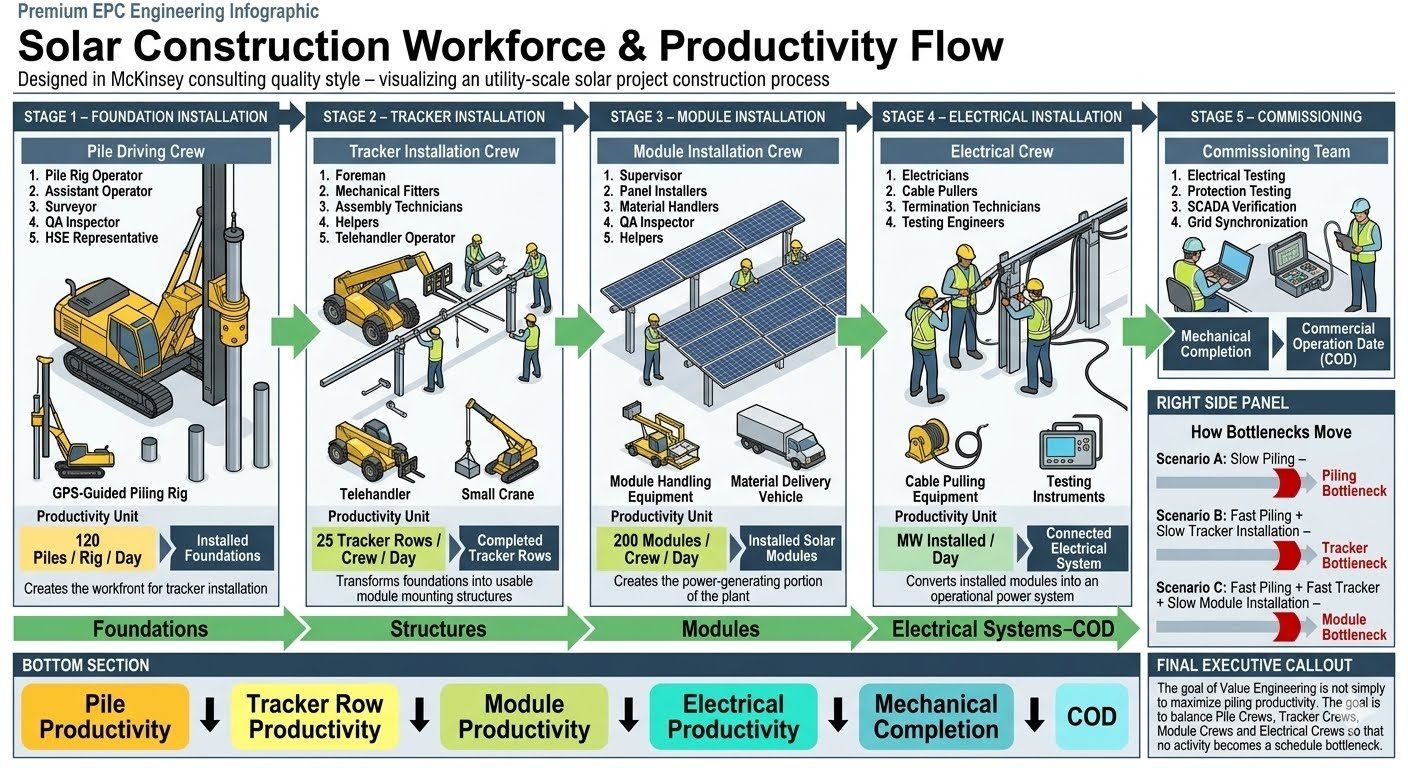
Solar Project Construction Workforce: Managing Five Sequential Execution Stages
In my two decades managing industrial and utility-scale energy construction sites, I have witnessed firsthand how labor synchronization dictates project success. When building a utility-scale solar project, the workforce flows through five sequential stages, each with its own dedicated crew and specialized heavy equipment. Understanding these distinct phases is essential for project managers, field engineers, and HSE professionals aiming to eliminate costly idle time.
Whether coordinating GPS-guided piling rigs or overseeing high-voltage electrical commissioning, site leadership must constantly monitor productivity metrics and dynamic constraints. If one crew outpaces its successor, the entire site suffers from localized material accumulation and severe labor inefficiencies.
Key Execution Takeaways
- Sequential Stage Optimization: Aligning crew output across foundation, tracker, and module teams.
- Dynamic Bottleneck Identification: Managing pace shifts where the slowest crew dictates total site velocity.
- Rigorous Quality and HSE Controls: Maintaining strict compliance with OSHA and IEEE standards during active deployment.
Solar Project Construction Workforce Execution and Crew Dynamics
Executing a multi-megawatt photovoltaic plant requires precise alignment between human resources, heavy machinery, and geotechnical site conditions. In my experience, treating each phase as an isolated silo guarantees site failure. Every crew operates as an interdependent link in a long chain, where output variations immediately ripple across the entire construction footprint.
Let us examine the specific staffing, equipment, and production metrics associated with each of the five core execution stages that govern modern utility-scale solar construction sites.
Stage 1: Foundation Installation and Geotechnical Control
The foundation stage sets the geometric baseline for the entire solar array. Rammed H-piles or driven steel posts must adhere to strict pull-out and lateral load tolerances defined by structural engineers. Deviations here propagate into severe mechanical binding during tracker installation.
- Crew Composition: Rig operator, assistant operator, topographic surveyor, QA inspector, and HSE representative.
- Core Equipment: GPS-guided hydraulic piling rig, total station survey kits, and pull-test dynamometers.
- Execution Focus: Real-time RTK-GPS alignment verifying pile depth, plumbness (within 0.5 degrees), and azimuth orientation.
Geotechnical Pull-Test Calculation Standard
Design pull capacity (P_allow) must exceed site uplift forces calculated under ASCE 7-22 wind load criteria. The QA inspector verifies proof load testing using the formula:
P_test = 1.25 * P_design (Held for minimum 3 minutes with max 1mm creep)
Failure to meet these thresholds mandates immediate refusal logging and engineering review before pile acceptance.
Stage 2: Tracker Row Installation and Mechanical Alignment
Once foundations pass inspection, the mechanical crew mounts torque tubes, slew drives, and bearing assemblies. This stage demands high mechanical dexterity to ensure smooth rotation profiles across single-axis tracker systems.
- Crew Composition: Foreman, mechanical fitters, assembly technicians, general helpers, and telehandler operator.
- Target Productivity: Benchmark output of 25 tracker rows per crew per day under normal soil and weather conditions.
- Critical Parameter: Torque wrench calibration verifying fastener preload per manufacturer specifications (e.g., Grade 8.8 hardware torqued to exact ft-lbs).
Stage 3: Module Installation and Panel Handling
Photovoltaic modules represent a massive capital expenditure, making material handling and micro-crack prevention paramount. Installers secure glass-glass or glass-backsheet modules onto purlins using specialized torque-limiting tooling.
- Crew Composition: Construction supervisor, panel installers, material handlers, QA inspector, and safety helpers.
- Target Productivity: Benchmark output of 200 modules per crew per day, synchronized with tracker structural readiness.
- Quality Gate: Zero tolerance for clamp over-torque, which induces micro-fissures in silicon wafers and causes long-term hot-spot degradation.
Stage 4: Electrical Installation and Home-Run Cabling
Electrical balance of system (EBOS) installation bridges the mechanical structures with power conversion stations. Electricians route string harnesses, install combiner boxes, and pull underground or tray-bound medium-voltage cables.
- Crew Composition: Certified electricians, cable pullers, termination technicians, and testing engineers.
- Scope of Work: DC string wiring, MC4 connector crimping verification, fiber optic backbone routing, and inverter pad grounding.
- Compliance Standard: Adherence to NFPA 70 (National Electrical Code) for conductor ampacity and conduit fill ratios.
Stage 5: Commissioning, Grid Synchronization, and Handover
The final operational phase verifies system readiness before commercial operation date (COD) sign-off. Testing specialists perform insulation resistance testing (Megger), IV curve tracing, protection relay calibration, and SCADA telemetry verification.
- Specialized Roles: Electrical testing specialists, protection engineers, SCADA integration technicians, and utility witness engineers.
- Deliverables: Mechanical completion certificates, commissioning sign-off reports, and grid synchronization permits.
Field Warning: Dynamic Workforce Bottleneck Shifts
Project pace is always set by whichever crew is currently the slowest link in the chain. In Scenario A, an underperforming tracker crew (e.g., 10 rows/day) becomes the absolute constraint, starving the module installation crew of mounting surfaces.
In Scenario B, if management accelerates the tracker crew past design thresholds (35 rows/day) without expanding downstream capacity, the bottleneck shifts directly to the module installation crew (capped at 200 modules/day), creating dangerous material congestion on site roads.
Structuring a utility-scale solar construction workforce into distinct, specialized stages offers profound advantages in operational speed and task mastery. However, it also introduces rigid interdependencies that require meticulous site management.
Advantages of Stage-Gate Crews
- High Task Proficiency: Crews repeating specialized steps daily achieve peak installation speed and muscle memory.
- Targeted Quality Control: QA inspectors can focus intensely on specific error modes relevant to each phase (e.g., pile plumbness vs. torque verification).
- Predictable Production Modeling: Standardized daily metrics (e.g., 200 modules/crew/day) allow precise schedule forecasting.
- Clear Accountability: Performance bottlenecks are easily isolated to specific team leads and equipment spreads.
- Optimized Equipment Utilization: Heavy assets like GPS piling rigs and telehandlers remain dedicated to active zones.
Disadvantages & Risk Factors
- Severe Interdependency Risk: A delay in Stage 1 immediately halts all downstream trades, causing costly labor idle time.
- Logistical Congestion: Pushing fast crews into tight spaces creates material staging bottlenecks and equipment traffic jams.
- High Supervisory Overhead: Each specialized crew requires dedicated supervision, safety reps, and specialized tooling packages.
- Rework Cascades: An undetected error in foundation alignment multiplies across thousands of subsequent tracker assemblies.
- Demobilization Friction: Transitioning personnel between distinct skill sets requires continuous workforce re-allocation.
The five-stage workforce model adapts dynamically to various utility-scale deployment environments. Below are four primary real-world application contexts where structured crew management determines project profitability.
Utility-Scale Desert Photovoltaic Mega-Projects (500MW+)
In vast flat terrain, linear progression allows crews to march across multi-square-mile footprints in synchronized waves. Foundation rigs lead by two miles, followed by tracker assembly and high-speed module installation teams.
This spatial separation prevents equipment congestion, allowing logistics teams to supply dedicated staging zones directly via peripheral site roads without disrupting active installation fronts.
Undulating Terrain and Sloped Hillside Solar Farms
Complex topography disrupts standard production rates, requiring dynamic re-allocation of foundation and tracker crews. Specialized survey teams work closely with piling rig operators to adjust pile heights for variable slope angles.
Module installers must adapt to staggered racking planes, requiring enhanced safety harnesses and specialized material lifting equipment to prevent panel damage on uneven ground.
Fast-Track Brownfield Industrial Solar Installations
Brownfield sites constrained by existing subterranean infrastructure or environmental remediation zones demand extreme precision from Stage 1 foundation crews. Ground penetration methods often shift from ramming to pre-drilling or ballasted concrete foundations.
Electrical teams coordinate closely with environmental compliance officers to ensure trenching and cable routing avoid capped or sensitive zones while maintaining aggressive construction schedules.
Remote Island and Microgrid Solar Deployments
Isolated sites with restricted logistical supply chains require rigorous workforce efficiency to prevent expensive charter delays. Commissioning and electrical testing specialists are embedded early to validate equipment integrity before final shipping containers depart.
Cross-training multi-skilled labor helps mitigate staffing shortages, allowing personnel to transition smoothly between tracker assembly and electrical termination tasks as project priorities shift.
Solar Workforce Productivity Metrics and Crew Allocation Standards
Utility-scale photovoltaic (USDOE Solar Energy Technologies Office) construction requires rigorous tracking of crew compositions, daily output targets, and equipment utilization rates to maintain schedule integrity across vast geographical footprints. In my experience managing multi-megawatt installations, failing to calibrate crew sizes against specific geotechnical and terrain profiles leads directly to cascading bottlenecks where upstream civil works overwhelm downstream electrical teams.
The following engineering reference table outlines the staffing models, primary plant, and baseline productivity benchmarks across all five sequential construction phases. These metrics align with standard ASME project management practices and OSHA safety governance frameworks.
| Construction Stage | Core Crew Composition | Primary Equipment | Baseline Daily Output | Governing Standard |
|---|---|---|---|---|
| Stage 1: Foundation Installation | Rig Operator, Assistant, Surveyor, QA Inspector, HSE Rep | GPS-Guided Piling Rig, Total Station, Telehandler | 120-150 Piles / Rig / Day | ASTM D3689 / OSHA 1926 |
| Stage 2: Tracker Row Assembly | Foreman, Mechanical Fitters, Assembly Techs, Helpers, Telehandler Op | All-Terrain Telehandler, Torque Wrenches, Impact Guns | 25 Tracker Rows / Crew / Day | Manufacturer Specs / ASME B30.5 |
| Stage 3: Module Installation | Supervisor, Panel Installers, Material Handlers, QA Inspector, Helpers | Module Lifters, Torque Guns, Scissor Lifts | 200 Modules / Crew / Day | IEC 62446 / UL 1703/61730 |
| Stage 4: Electrical Installation | Licensed Electricians, Cable Pullers, Termination Techs, Testers | Cable Pullers, Megohmmeters, Crimping Tools | 1.5 MW DC Cable / Day | NFPA 70 (NEC) |
| Stage 5: Commissioning | Electrical, Protection, SCADA, and Grid Synchronization Specialists | Relay Test Sets, SCADA Workstations, Power Quality Analyzers | Complete Substation & Inverter Block / 3 Days | IEEE 1547 / NERC Reliability Standards |
Note that baseline output rates assume level, stable soil conditions with minimal rock refusal. When encountering high plasticity clays or hard caliche layers, foundation installation rates frequently drop by 40%, requiring immediate re-balancing of downstream tracker and module crews to prevent severe site congestion.
Technical Mapping & Specifications Matrix
To maintain absolute clarity across engineering disciplines during complex utility-scale deployments, managing structural interfaces requires a standardized entity mapping matrix. This framework categorizes physical assets, software platforms, and regulatory codes into interoperable nodes, ensuring seamless data transfer between site supervisors and central project controls.
The matrix below outlines the primary technological, mechanical, and electrical entities governing multi-stage workforce flows. Each entity represents a critical control point where quality assurance (ASQ) and health, safety, and environment (OSHA) protocols intersect with daily construction productivity.
| Entity Classification | Structural Acronym | Primary Physical Parameter | Governing Code / Standard | Operational Tolerance |
|---|---|---|---|---|
| Global Positioning System Pile Drive | GPS-PD | Verticality & Embedment Depth | ASTM D3689 | Plus or Minus 0.5 Degrees Plumb |
| Single-Axis Tracker Actuation | SATA | Torque Tube Alignment & Deflection | ASCE 7-22 | Plus or Minus 2 mm Bearing Offset |
| Photovoltaic Module Mounting | PVM | Clamping Pressure & Micro-Crack Prevention | IEC 61215 | Exact Torque Spec per Bolt Grade |
| Direct Current Home Run Cable | DCHC | Insulation Resistance & Voltage Drop | NFPA 70 | Greater than 100 Megaohms at 1kV |
| Supervisory Control And Data Acquisition | SCADA | Communication Latency & Signal Integrity | IEEE 1547 | Sub-Second Polling Response Time |
Maintaining strict adherence to these tolerances prevents structural fatigue under wind loading and ensures electrical safety compliance throughout the thirty-year operational lifespan of the solar facility.
Site Verification Checklist for Sequential Solar Workforce Flows
Effective management of sequential utility-scale solar construction requires rigorous stage-gate verification to ensure that crews do not release substandard work to downstream teams. As a piping and mechanical engineering expert, I rely on structured audit protocols to identify workflow bottlenecks before they disrupt overall project velocity.
Execute the following inspection checkpoints across all five construction stages, validating compliance against OSHA and ASME guidelines before granting sign-off for downstream crew deployment.
Phase-by-Phase Site Verification Protocol
-
Stage 1 Foundation Piling Verification: Validate GPS rig calibration and inspect embedment depth, plumbness, and pull-out resistance per ASTM D3689 standards prior to tracker mounting release.
-
Stage 2 Tracker Row Alignment Check: Verify torque tube rotational freedom, bearing fastener torque values, and drive-motor synchronization across all assembled rows before module handoff.
-
Stage 3 Module Installation Inspection: Conduct 100 percent visual surface checks for micro-cracks and ensure all module mounting hardware achieves exact specified torque per IEC 62446 guidelines.
-
Stage 4 Electrical Termination Audit: Perform megohm insulation resistance testing on all DC strings and verify proper polarity and torque on all combiner box connections per NFPA 70.
-
Stage 5 Commissioning and Grid Sync: Execute protection relay coordination tests, SCADA communication latency verification, and inverter synchronization per IEEE 1547 prior to commercial operation date sign-off.
-
Bottleneck Analysis and Crew Balancing: Review daily production logs to identify pacing constraints between tracker and module crews, reallocating telehandlers and helpers to eliminate the current slowest link in the chain.
Site supervisors must sign off on each checklist item digitally in the project management portal. Bypassing any step in this sequence inevitably results in costly rework during high-voltage energization or warranty claims during commercial operation.
Field Case Study: Real-World Application
During the construction of a 300-megawatt utility-scale photovoltaic facility in the desert Southwest, our project management team encountered severe workflow friction caused by unbalanced crew allocation between Stage 2 tracker assembly and Stage 3 module installation.
Understanding how bottlenecks shift between crews is essential for maintaining mechanical completion schedules and achieving timely commercial operation date sign-off under strict engineering standards.
Field Problem: Shifting Bottlenecks and Crew Velocity Mismatches
The project suffered from erratic production rates where overall pace stalled due to uncalibrated crew sizing and equipment shortages across sequential work fronts.
- Scenario A Constraint: An understaffed tracker assembly crew managed only 10 rows per day against a target of 25, creating an upstream bottleneck that starved the module installation crew of ready torque tubes.
- Scenario B Constraint: After management added mechanical fitters to accelerate Stage 2 output to 35 rows per day, the bottleneck abruptly shifted downstream because the module installation crew remained capped at 200 modules per day.
- Equipment Contention: A single all-terrain telehandler was shared between tracker assembly and module staging, leading to idle time for assembly technicians waiting for material lifts.
- Quality Inspection Lag: QA inspectors fell behind on verifying pile verticality per ASTM D3689, forcing mechanical fitters to halt alignment work while awaiting engineering dispositions.
Field Outcome: Dynamic Crew Balancing and Milestone Achievement
Implementing a dynamic resource leveling strategy resolved the pacing constraints and restored predictable daily output across all five construction stages.
- Pacing Alignment: Rebalanced crew ratios to match Stage 2 tracker output (25 rows/day) with Stage 3 module capacity (200 modules/day), eliminating idle labor hours.
- Equipment Dedicated Allocation: Assigned dedicated telehandlers to each stage, preventing material handling bottlenecks and increasing daily hoist efficiency by 30 percent.
- Streamlined QA Sign-Off: Implemented digital sign-off portals on mobile tablets for QA inspectors, reducing foundation verification turnaround time from 24 hours to under 2 hours.
- Commercial Success: Delivered mechanical completion and secured commercial operation date sign-off two weeks ahead of schedule while maintaining full compliance with IEEE 1547 grid interconnection standards.
Recommendation: Always monitor the immediate constraint in your construction chain rather than optimizing isolated crews. Project velocity is strictly governed by whichever crew or equipment spread represents the slowest active link at any given time.
Frequently Asked Engineering Questions
How do you manage crew balancing across sequential solar construction stages?
- Track daily linear meter output for piling and tracker installation crews.
- Adjust module handler counts dynamically to match tracker mechanical completion rates.
- Maintain buffer zones between civil foundations and electrical termination teams.
What causes productivity bottlenecks during tracker row installation?
- Inadequate telehandler availability slows down torque tube distribution.
- Uncalibrated torque wrenches cause cascading QA rework loops.
- Uneven pile embedment depths force manual shimming during torque tube alignment.
How can module installation rates be scaled safely on utility projects?
- Deploy mechanical glass lifters for large-format bifacial solar modules.
- Enforce strict torque limits on module mid-clamps to prevent micro-cracking.
- Rotate panel installation crews every two hours to mitigate fatigue.
What qualifications are mandatory for electrical commissioning teams?
- Require NETA Level III certification for primary high-voltage testing leads.
- Mandate specialized training for SCADA communication protocol verification.
- Enforce strict Lockout/Tagout procedures during string insulation testing.
How does shifting bottleneck crews impact overall solar project schedule?
- Excess tracker output creates unpopulated rows if module crews are understaffed.
- Over-resourcing piling rigs overwhelms surveying teams with verification backlogs.
- Schedule stability depends on synchronizing crew capacities to match inverter commissioning dates.
Based on two decades of utility-scale construction oversight, I advise project directors to manage workflow sequencing by continuously auditing crew output ratios rather than chasing individual daily production records. If geotechnical variance slows down Stage 1 piling, do not surge labor into Stage 2 tracker assembly; instead, reallocate surplus mechanics to support pre-assembly operations until foundation velocity stabilizes.
- If geotechnical refusal rates exceed 15 percent in rocky subgrades, immediately deploy supplementary pre-drilling rigs before expanding the primary pile driving crew to prevent downstream starvation.
- If module installation rates outpace electrical termination capacity, cap daily panel mounting to avoid exposing un-terminated DC home runs to moisture and environmental degradation over extended periods.
- If high-voltage testing resources become limited during peak commissioning, prioritize inverter blocks nearest the point of interconnection to accelerate grid synchronization milestones.
- If mechanical torque verification delays threaten the critical path, mandate dual-shift QC inspection routines rather than halting tracker row assembly entirely.
Complete Course on
Piping Engineering
Check Now
Key Features
- 125+ Hours Content
- 500+ Recorded Lectures
- 20+ Years Exp.
- Lifetime Access
Coverage
- Codes & Standards
- Layouts & Design
- Material Eng.
- Stress Analysis
