Solar Power Plant Commissioning: From Mechanical Completion to Commercial Operation
In my two decades managing heavy industrial and renewable energy construction, I have observed a recurring misconception: assuming that a physically erected solar farm is ready to generate revenue. In reality, mechanical completion simply means the nuts are tightened and cables are pulled. True asset readiness requires rigorous solar power plant commissioning, a structured validation phase that proves every string, inverter, transformer, and SCADA point operates safely and efficiently before utility interconnection.
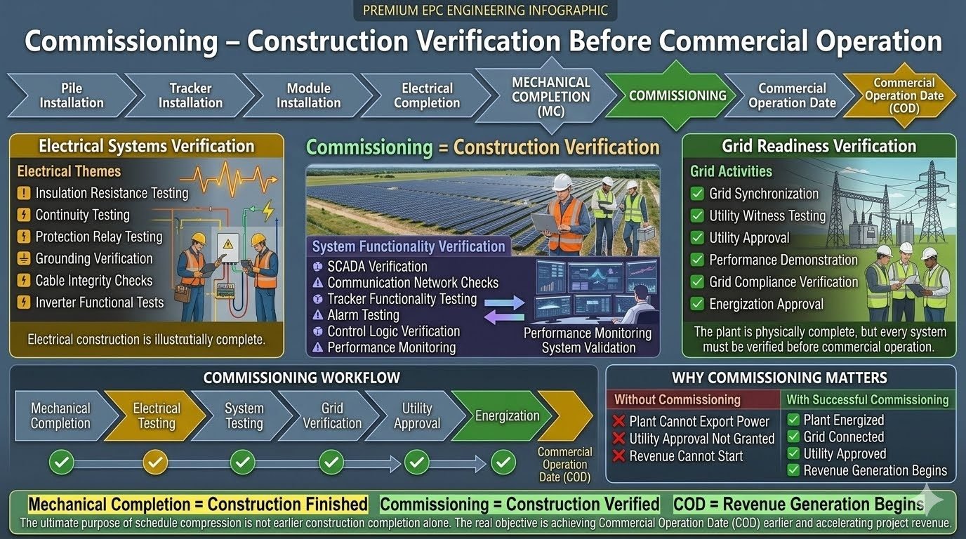
Commissioning is construction verification, not construction itself. Without this multi-tiered testing sequence, utility grid operators will withhold synchronization approval, leaving multi-million-dollar assets idle. Throughout this guide, I will break down the essential electrical testing, system functionality checks, and grid compliance milestones required to achieve a seamless Commercial Operation Date (COD).
Key Commissioning Takeaways
- Mechanical Completion vs Commissioning: Construction finished versus construction verified.
- Three Core Verification Pillars: Electrical systems, system functionality, and grid readiness.
- The Ultimate Milestone: Passing utility witness testing to unlock commercial revenue generation.
Electrical Systems and Grid Readiness Verification Protocols
Executing a successful photovoltaic facility startup demands a disciplined engineering workflow. As a commissioning authority, I establish strict boundaries between mechanical punch-listing and live electrical verification. The transition from a static construction site to an energized power plant involves progressive stages of testing, where any oversight can lead to catastrophic arc flashes or regulatory rejection.
The process begins immediately after mechanical completion is signed off. At this juncture, the civil works, module mounting, DC string cabling, medium-voltage AC reticulation, and substation installations are complete. However, no equipment has yet been energized. The focus shifts entirely to proving insulation integrity, circuit continuity, and control logic responsiveness.
Electrical Systems Verification Phase
Electrical testing forms the bedrock of safety and reliability. Before applying any voltage, technicians must execute insulation resistance testing—commonly known as Megger testing—on all DC home runs, AC collector cables, and power transformer windings.
Core Electrical Testing Parameters
- Insulation Resistance: DC string testing performed at 1000V DC minimum; MV cables tested per ICEA S-93-639 standards.
- Continuity Testing: Verifying equipment grounding conductors, metallic racking bonds, and shield continuity to maintain earth fault loop impedance limits.
- Protection Relay Testing: Secondary injection testing of all overcurrent, earth fault, and directional relays inside the main substation switchgear.
- Cable Integrity Checks: High-potential (Hipot) testing and Time Domain Reflectometry (TDR) on medium-voltage underground cables prior to termination hookups.
Following insulation checks, inverter functional tests are performed. Central or string inverters are powered up using auxiliary auxiliary power supplies (UPS) to test internal cooling fans, DC switchgear, emergency stop loops, and MPPT tracking channels before DC strings are connected.
System Functionality Verification Phase
Once the electrical grid infrastructure is verified, attention shifts to software, communication, and control systems. A modern utility-scale solar plant is a digital ecosystem. If the SCADA network fails to poll meteorological stations or inverter data logs, plant operators lose situational awareness and automatic generation control (AGC) capabilities.
SCADA verification requires end-to-end point-to-point signal mapping. Every sensor reading—from plane-of-array irradiance sensors and ambient temperature probes to revenue meter pulse outputs—must register accurately on the central control room human-machine interface (HMI). Tracker functionality verification is conducted simultaneously, commanding single-axis trackers through full rotational sweeps (east to stow) while monitoring motor current draw and limit switch accuracy.
Engineering Warning: Ground Fault Hazards During Testing
Never perform high-voltage insulation resistance testing on DC strings while inverter DC disconnects are closed. Doing so will permanently destroy sensitive semiconductor switching modules within the inverter power stack. Always isolate all semiconductor equipment using lock-out tag-out (LOTO) protocols before applying megger test voltages.
Grid Readiness and Utility Synchronization
The final hurdle before commercial operation is grid synchronization. This phase requires close coordination with the transmission system operator (TSO) or local utility distribution company. Utility witness testing is mandatory, where utility engineers observe tripping tests, reactive power injection, and anti-islanding protection verification.
Compliance with grid codes is non-negotiable. Inverters must demonstrate fault ride-through (FRT) capabilities, dynamic voltage support, and active power curtailment responsiveness. Once utility witness testing is successfully documented, the plant receives formal grid compliance approval and energization authorization, allowing the high-voltage step-up transformer to be energized from the grid side.
The commissioning sequence culminates in the performance demonstration test, where the plant operates continuously at design capacity for a stipulated reliability period (typically 7 to 30 days). Passing this trial confirms the plant’s PR (Performance Ratio) and paves the way for the Commercial Operation Date (COD), formally transferring the asset from construction management to operations and maintenance (O&M).
Solar Plant Commissioning Test Parameters and Standards
The following engineering matrix outlines the critical test parameters, acceptable thresholds, and governing industry standards utilized during utility-scale solar plant commissioning.
| Test Category | Parameter Monitored | Acceptance Criteria | Governing Standard |
|---|---|---|---|
| DC Insulation Resistance | String Conductor to Ground | > 50 Megaohms at 1000V DC | IEC 62446-1 |
| MV Cable Testing | VLF / Hipot & Shield Continuity | Zero breakdown at test voltage | IEEE 400.3 |
| Transformer Testing | Turns Ratio & Dissipation Factor | Within 0.5% of nameplate rating | IEEE C57.12.90 |
| Grid Synchronization | Phase Angle & Voltage Match | Delta V < 2%, Delta Frequency < 0.1Hz | NERC Reliability Stds |
| SCADA Point-to-Point | Signal Latency & Accuracy | 100% signal mapping verification | Modbus TCP / DNP3 |
Technical Mapping and Specifications Matrix
This entity matrix correlates primary engineering subsystems with their corresponding testing objectives, diagnostic tools, and regulatory validation bodies.
| Subsystem Entity | Diagnostic Tool | Key Parameter | Compliance Authority |
|---|---|---|---|
| Photovoltaic Array | I-V Curve Tracer | Fill Factor & Shunting Resistance | IEC 61829 |
| Inverter Station | Power Analyzer & Scope | Total Harmonic Distortion (THD) | IEEE 519 |
| Substation Switchgear | Secondary Injection Set | Trip Time & Pickup Current | NETA MTS |
| Meteorological Station | Pyranometer Calibrator | Irradiance W/m2 Accuracy | WMO Guidelines |
Advantages & Disadvantages
Advantages of Rigorous Commissioning
- Early Fault Detection: Identifies defective DC cabling, loose busbar torques, and faulty microprocessors before catastrophic failure occurs under full load.
- Utility Compliance Assurance: Guarantees smooth utility witness testing and fast-tracks grid synchronization approvals without costly re-testing delays.
- Maximized Energy Yield: Validates tracker alignment and pyranometer calibration to ensure accurate performance ratio calculations.
- Warranty Protection: Establishes baseline test records that satisfy equipment manufacturer warranty requirements for inverters and transformers.
- Enhanced Personnel Safety: Prevents arc flash incidents and ground faults through rigorous insulation and relay protection verification.
Disadvantages & Challenges
- Schedule Compression Pressure: Strict project timelines often squeeze the commissioning window, creating intense pressure on engineering teams.
- High Specialized Equipment Costs: Requires expensive diagnostic tools such as I-V curve tracers, VLF hipot testers, and thermal imaging cameras.
- Skilled Labor Shortages: Finding certified electrical testing technicians familiar with high-voltage utility standards can delay project execution.
- Grid Interconnection Bottlenecks: TSO scheduling delays for witness testing can postpone Commercial Operation Dates despite physical site readiness.
- Weather Dependency: Testing active power output and thermal performance requires stable irradiance windows, complicating overcast or rainy schedules.
Real-World Applications
Utility-Scale Ground-Mounted Solar Parks
Mega-watt scale solar farms interconnected at transmission voltages (> 33kV) require extensive substation commissioning, breaker coordination studies, and SCADA-to-grid operator telemetry links. Rigorous testing prevents widespread grid disturbances and ensures NERC compliance during sudden generation dropouts.
Commercial and Industrial Rooftop Arrays
C&I rooftop installations demand rigorous structural dead-load verification combined with rapid shutdown compliance testing per NFPA 70. Commissioning ensures that building electrical fire safety systems interface correctly with string-level DC isolators.
Hybrid Solar and Battery Energy Storage Systems (BESS)
Coupling photovoltaic generation with lithium-ion storage introduces complex bi-directional power flow commissioning. Testing focuses on seamless switching between grid-tied and islanded modes, battery management system (BMS) alarm integration, and fast frequency response validation.
Remote Island and Microgrid Installations
Isolated microgrids rely on advanced solar-diesel hybrid controls during commissioning. Engineers must verify load-sharing algorithms, spinning reserve response, and black-start capabilities to ensure uninterrupted power delivery without a robust main utility grid backing the system.
Commissioning Testing Parameters and Acceptance Criteria
Systematic testing during the commissioning phase requires adherence to rigorous electrical and mechanical thresholds established by international standards such as IEC 62446 and IEEE 1547. In my experience managing utility-scale photovoltaic installations, documenting these baseline metrics prevents premature degradation and ensures compliance with grid interconnection agreements before utility witness testing commences.
The engineering data table below details the primary test categories, associated instrumentation, standard operating limits, and governing codes. Every parameter must be verified and signed off by the quality control inspector prior to submitting documentation packages for final utility approval.
| Test Category | Parameter Monitored | Acceptance Criteria | Governing Standard |
|---|---|---|---|
| Insulation Resistance | DC Cable & Module Strings | > 1 Megaohm at 1000V DC test voltage | IEC 62446-1 |
| Ground Continuity | Racking and Equipment Bonding | < 0.1 Ohms resistance path to main grid ground | NFPA 70 / NEC 690 |
| Inverter Synchronization | Voltage, Frequency, Phase Angle | Within +/- 0.5 Hz and +/- 2% nominal voltage | IEEE 1547 |
| Protection Relay Trip | Over/Under Voltage & Frequency | Actual trip time within +/- 10ms of setpoint | IEEE C37.90 |
| SCADA Data Latency | Signal Polling & Alarm Response | End-to-end telemetry update rate < 2 seconds | IEC 61850 |
Reviewing these metrics during initial dry commissioning runs ensures that harmonic distortion and power factor anomalies are identified before energization. Any deviation from these specified limits requires an immediate root cause analysis and hardware recalibration.
Technical Mapping & Specifications Matrix
Navigating the transition from mechanical completion to utility grid synchronization requires a structured entity mapping framework. This matrix correlates major subsystem acronyms, physical parameters, verification tools, and regulatory milestones to ensure comprehensive project visibility.
The mapping specifications below establish a standardized nomenclature for project engineering teams, independent engineers, and utility witnesses during on-site audit procedures.
| System Entity | Primary Acronym | Core Function | Verification Protocol |
|---|---|---|---|
| Supervisory Control and Data Acquisition | SCADA | Centralized plant monitoring and remote control | End-to-end signal mapping and loop verification |
| Commercial Operation Date | COD | Initiation of revenue generation and power sales | Utility sign-off and power purchase agreement execution |
| Mechanical Completion | MC | Physical construction and hardware installation finish | Punch-list walkthrough and structural torque audit |
| Inverter Station Medium Voltage | PCU / MVS | DC to AC conversion and voltage step-up transformation | Megger testing, oil sampling, and functional trips |
| Interconnection Protection Relay | SEL / IED | Grid fault isolation and anti-islanding protection | Secondary injection testing and trip timing verification |
Maintaining this rigorous entity mapping across engineering design submittals and site test reports guarantees a seamless handoff to operations and maintenance teams following commercial energization.
Solar Power Plant Site Verification Checklist
Executing a flawless commissioning phase demands strict adherence to sequential site verification checkpoints. Before requesting utility witness testing, my engineering teams systematically verify every physical connection and software logic link against approved construction drawings and regulatory mandates.
The structured checklist below outlines the mandatory validation rules required to transition an installation safely from mechanical completion through electrical testing to final grid synchronization.
Pre-Energization and System Verification Steps
- 1. Mechanical Punch-List Clearance: Verify all structural torque markings, module clamp tightness, and tracker alignment meet manufacturer specifications.
- 2. DC Cable Insulation Testing: Perform 1000V DC megger testing on all home-run conductors and record ambient temperature correction factors.
- 3. Grounding Grid Continuity Audit: Measure earth electrode resistance using fall-of-potential method to ensure values remain below 1 ohm.
- 4. Protection Relay Secondary Injection: Validate trip curves and communication signals for all interconnected utility feeder relays.
- 5. SCADA and RTU Signal Mapping: Confirm real-time telemetry updates for active power, reactive power, and inverter status without packet loss.
- 6. Utility Witness Sign-Off: Obtain formal written approval of test results from the transmission system operator prior to main breaker closure.
Completing this verification protocol eliminates costly utility re-inspection delays and safeguards personnel during high-voltage energization. Keep signed copies of each checklist item in the permanent plant engineering archive.
Field Case Study: Utility-Scale Solar Plant Commissioning Challenge
During the commissioning phase of a 150MW utility-scale photovoltaic facility in the southwestern desert, our engineering team encountered a critical synchronization failure during the final grid compliance testing window.
Problem Statement:
Unanticipated harmonic interference triggered premature inverter trip events during utility witness testing, halting the grid synchronization sequence.
- Inverter output voltage harmonics exceeded IEEE 1547 distortion limits by 3.2 percent.
- Grid support protection relays falsely interpreted harmonic spikes as an islanding condition.
- SCADA polling latency spiked to 4.5 seconds under full active power load testing.
- Utility representatives suspended witness testing pending a comprehensive harmonic mitigation plan.
To resolve this issue without missing our contractual Commercial Operation Date, we immediately mobilized our electrical testing specialists to perform root cause analysis and coordinate firmware adjustments with the inverter manufacturer.
Outcome & Results:
Implementing targeted harmonic filtering and updating inverter control algorithms successfully restored grid compliance and secured unconditional utility approval.
- Total Harmonic Distortion reduced from 6.8 percent down to 1.8 percent, well below the 5 percent ceiling.
- Successfully passed re-test of utility witness protocols within 72 hours of hardware recalibration.
- Achieved full grid synchronization and permanent plant energization without incurring liquidated damages.
- Commercial Operation Date achieved exactly on schedule, unlocking immediate power purchase revenue.
Recommendation: Always incorporate preliminary harmonic spectrum scans during dry commissioning runs before scheduling formal utility witness testing to prevent costly scheduling delays and revenue deferral.
Frequently Asked Engineering Questions
What is the exact distinction between Mechanical Completion and solar power plant commissioning?
- Mechanical Completion: All mounting structures, panels, cables, and inverters are physically bolted and terminated.
- Commissioning Stage: Insulation resistance, functional loop checks, and control logic verification take place.
- Handover Boundary: Contractors sign over physical custody during mechanical completion, whereas plant owners take over operational readiness post-commissioning.
Which electrical testing procedures are mandatory before inverter energization?
- Insulation Resistance Testing: Megger testing of DC string cables and AC feeder cables per IEEE 43 standards.
- Continuity and Grounding Verification: Ensuring low-resistance earth mat paths and bonded metallic structures.
- Protection Relay Testing: Secondary injection testing to confirm trip settings match utility interconnection requirements.
How does SCADA verification impact the grid synchronization timeline?
- Data Point Mapping: All telemetry signals, active power limits, and reactive power setpoints must map accurately.
- Communication Redundancy: Fiber optic and cellular links require latency testing to meet strict utility dispatch rules.
- Alarm Verification: Critical fault signals must report to the control center within mandated response windows.
What constitutes a successful utility witness test during grid readiness verification?
- Trip Testing: Manually tripping breakers to verify auxiliary transfer and anti-islanding protection.
- Harmonic and Voltage Flicker Analysis: Proving that inverter output meets local grid code limits.
- Ramp Rate Verification: Demonstrating that plant output changes smoothly without causing grid voltage surges.
What are the financial and operational stakes of skipping formal commissioning steps?
- Revenue Delays: The Commercial Operation Date (COD) cannot be declared without official utility energization approval.
- Equipment Damage: Undetected ground faults or phase imbalances can destroy expensive inverters and transformers instantly.
- Regulatory Penalties: Unauthorized grid connection can lead to heavy utility fines and permanent interconnection revocation.
Field Recommendation
- Mandate Independent Insulation Testing: If sub-contractor schedules are compressed, never allow internal Megger test reports to substitute for witness-verified DC string insulation checks, because trapped moisture in cable trenches frequently causes ground-fault trips during the first rain cycle post-energization.
- Engage Grid Operators Early on SCADA Protocols: When executing utility communication architecture, require your automation engineers to complete point-to-point telemetry mapping at least four weeks prior to the scheduled witness test, preventing costly on-site delays caused by mismatched register addresses.
- Enforce Strict Anti-Islanding Verification: During protection relay commissioning, always prioritize physical breaker trip injection tests over software simulation logs, as actual hardware response times dictate whether the local utility will sign off on immediate grid parallel operation.
- Stagger Inverter Block Energization: If dealing with multi-megawatt utility-scale solar arrays, commission and energize inverter blocks sequentially rather than simultaneously, allowing your engineering team to isolate harmonic anomalies and voltage flicker issues before they trigger substation-wide lockouts.
- Tie Contractor Retainage Directly to COD: When structuring EPC handovers, withhold final contractor retention payments strictly until utility compliance approval and full commercial operation date certification are formally issued, ensuring zero loose ends in punch-list completion.
Complete Course on
Piping Engineering
Check Now
Key Features
- 125+ Hours Content
- 500+ Recorded Lectures
- 20+ Years Exp.
- Lifetime Access
Coverage
- Codes & Standards
- Layouts & Design
- Material Eng.
- Stress Analysis
