Engineering Solar Plant Electrical Systems: DC, AC, and SCADA Scopes
In my two decades managing heavy industrial and renewable energy construction, I have observed that the successful energization of a utility-scale solar facility relies entirely on the disciplined execution of three parallel electrical scopes. Coordinating the DC collection, AC power conversion, and digital control networks prevents costly commissioning delays.
When executing these installations, engineering teams must maintain strict adherence to insulation coordination, ampacity derating, and grounding integrity across every subsystem. Below, I break down the rigorous technical requirements governing each phase of the electrical crew’s scope.
Key Engineering Takeaways
- DC side works demand strict voltage drop calculations under NEC Article 690 guidelines.
- AC conversion networks must account for harmonic distortion and transformer vector group matching.
- SCADA and fiber optic networks require redundant fiber routing to ensure uninterrupted plant telemetry.
- Formal deliverables such as the DC System Complete milestone precede rigorous pre-energization testing.
Technical Deep-Dive: Solar Plant Electrical Systems Architecture
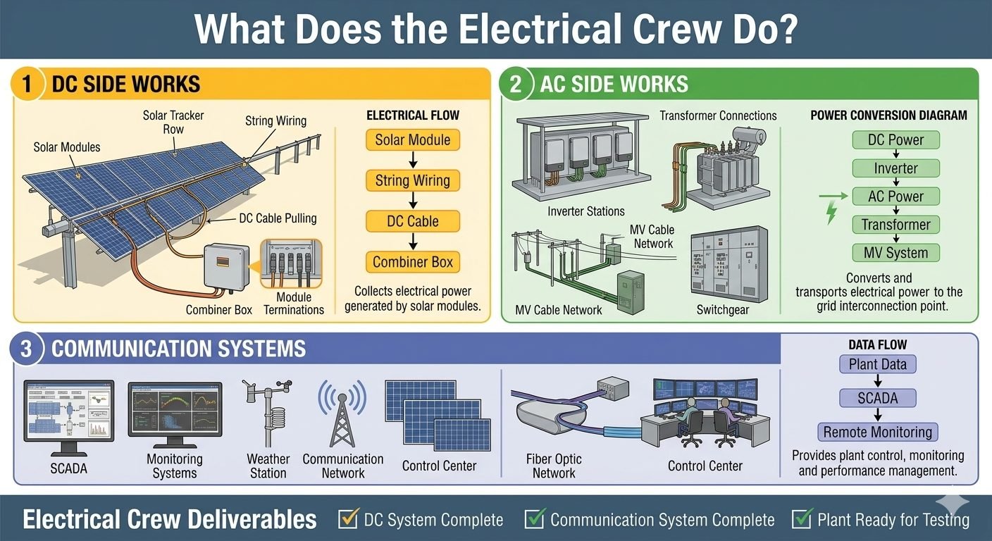
Designing a high-voltage photovoltaic balance of plant requires treating the electrical infrastructure as a continuous energy conversion continuum. The electrical crew’s work divides into three parallel scopes: DC Side Works, AC Side Works, and Communication Systems, each demanding distinct engineering methodologies.
1. DC Side Works and Combiner Box Engineering
DC Side Works begins at the solar modules, flows through string wiring, photovoltaic-rated DC cables, and terminates inside the combiner box. The combiner box aggregates electrical power generated by multiple strings of modules before routing the combined current to the central or string inverters.
When calculating conductor sizes for string and main DC cables, engineers must apply temperature correction factors and bundle derating coefficients as outlined in NFPA 70. Voltage drop across the DC array should never exceed 1.5 percent under maximum power point tracking conditions to preserve overall generation efficiency.
Critical Design Warning: DC Arc-Flash Mitigation
Unalleviated DC faults present severe arc-flash hazards because DC current lacks a natural zero-crossing point. Engineers must specify listed DC disconnects and rapid shutdown devices conforming to UL 3741 standards to ensure rapid arc extinction during fault conditions.
2. AC Side Works and Power Conversion Stations
AC Side Works covers inverter stations, the Medium Voltage cable network, and substation switchgear. The operation follows a strict Power Conversion Diagram: DC power flows into the inverter, which converts it to AC power, which then passes through a step-up transformer into the MV system for onward transport.
Inverter selection dictates the harmonic profile injected into the medium voltage network. Per IEEE 519, total harmonic distortion at the point of common coupling must remain below five percent. Step-up transformers must feature appropriate vector groups, such as Dyn11 configurations, to suppress zero-sequence harmonic currents.
3. Communication Systems and SCADA Integration
Communication Systems covers SCADA servers, monitoring systems, a meteorological weather station, the main control center, and a robust fiber optic network. The data flow requires plant operational data to feed into the local SCADA controller and then into remote monitoring dashboards.
This architecture provides comprehensive plant control, real-time performance monitoring, and automated curtailment management. Fiber optic cables must be armored and installed in dedicated conduits, maintaining strict separation from high-voltage AC power trays to eliminate electromagnetic interference.
4. Electrical Crew Deliverables and Commissioning Milestones
To achieve systematic project handover, the electrical crew must hit three mandatory completion milestones. These milestones form the contractual boundary between construction completion and electrical pre-energization testing:
- DC System Complete: Verified insulation resistance testing, torque verification on all combiner box lugs, and polarity validation across every home-run cable.
- Communication System Complete: End-to-end fiber optic attenuation testing, SCADA tag mapping verification, and weather station sensor calibration.
- Plant Ready for Testing: Final clearance of all safety interlocks, lockout tagout verification, and completion of all punch-list items across the AC switchgear.
Engineering Advantages
- Modular DC combiner architecture reduces copper weight and overall material expenditures.
- Decentralized inverter placement minimizes high-voltage DC run lengths across massive footprints.
- Redundant fiber optic communication rings ensure zero data loss during high-fault transients.
- Standardized milestone deliverables accelerate third-party electrical inspection approvals.
- Precise harmonic filtering on AC stations protects local grid stability and compliance.
Engineering Disadvantages
- High vulnerability to localized DC ground faults requiring specialized diagnostic equipment.
- Complex fiber optic termination demands certified technicians and delicate fusion splicing.
- Stringent thermal management required for outdoor inverter stations in extreme climates.
- Extended troubleshooting timelines when tracking intermittent telemetry failures across SCADA nodes.
- Rigorous torque auditing demands continuous re-verification due to thermal cycling stresses.
Utility-Scale Desert Photovoltaic Plants
Utility-scale installations spanning hundreds of hectares rely heavily on synchronized DC collection and medium-voltage AC conversion networks. The implementation of robust combiner box layouts and centralized inverter stations ensures efficient power transmission over vast geographic expanses while maintaining compliance with international grid connection codes.
Commercial Rooftop Solar Microgrids
Commercial and industrial rooftop systems integrate string inverters with localized SCADA monitoring to balance onsite loads. By utilizing advanced weather station telemetry and fiber optic backbones, facility managers achieve real-time performance optimization and immediate fault isolation during sudden grid fluctuations.
Agrivoltaic Dual-Use Installations
Agrivoltaic facilities present unique mechanical and electrical routing challenges due to elevated mounting structures and agricultural machinery operations. Specialized DC cable routing and armored underground medium voltage pathways protect the electrical infrastructure from mechanical damage while supporting combined agricultural and energy production.
Floating Solar Photovoltaic Farms
Floating solar installations deploy specialized floating DC combiner boxes and flexible sub-aquatic AC cabling to connect pontoon-mounted inverters to shore-based substations. Waterproof enclosures and corrosion-resistant metallic armor ensure long-term reliability in high-humidity aquatic environments.
Hybrid Solar and Battery Storage Facilities
Coupling solar generation with battery energy storage systems requires highly synchronized SCADA communication networks and bidirectional power conversion stations. Integrated control architectures manage DC charging cycles and AC grid injection simultaneously, optimizing plant revenue and dispatchability.
Solar Plant Electrical Infrastructure Specifications
Designing a utility-scale solar facility requires stringent adherence to electrical parameters across all three core scopes: DC collection, AC conversion, and plant-wide communication. In my experience reviewing grid-connection submittals, underestimating cable voltage drop or thermal derating factors is the single most common cause of pre-commissioning failure. The engineering data table below outlines the critical electrical parameters, standard conductor sizing limits, and governing codes for each subsystem.
Every parameter listed aligns with strict utility interconnect requirements and international standards. Engineers must verify that ambient temperature corrections and conduit fill calculations are applied prior to issuing final cable schedules to the construction crew.
| Subsystem Domain | Parameter / Component | Typical Engineering Limit | Governing Standard |
|---|---|---|---|
| DC Side Works | String Conductor (XLPO) | 1500V DC Max, 90°C Conductor Rating | UL 4703 / IEC 62930 |
| DC Side Works | Combiner Box Busbar | Tin-plated copper, max 2.5kA fault rating | IEC 61439-2 |
| AC Conversion | Central Inverter Output | 600V to 800V AC, 3-phase, 50/60 Hz | IEEE 1547 |
| AC Conversion | Step-Up Transformer | MV Side: 33kV / LV Side: 690V, ONAN | IEC 60076 |
| MV Cable Network | Underground MV Circuit | 35kV XLPE Insulated, Copper Wire Shield | IEC 60502-2 |
| Communication | Fiber Optic Backbone | Singlemode OS2, armored direct burial | TIA/EIA-568 |
Note: All conduit fill ratios and ampacity derating calculations must account for local soil thermal resistivity and ambient temperature extremes as specified in project design briefs.
Technical Mapping & Specifications Matrix
Managing a utility-scale solar installation requires flawless tracking of technical entities and hardware designations. During my site audits, I rely on a structured entity matrix to cross-reference physical installation assets with their governing engineering standards and software protocols. This eliminates ambiguity between civil, electrical, and control engineering teams during punch-list walkthroughs.
The specification matrix below maps out core plant entities, their standardized acronyms, physical operational parameters, and primary international compliance benchmarks.
| System Entity | Standard Acronym | Primary Physical Parameter | Governing Standard |
|---|---|---|---|
| Photovoltaic Module String | PV-STR | Voc up to 1500V DC, Imp ~13A | IEC 61215 |
| Direct Current Combiner Box | DC-CB | Input fusing up to 32 strings per box | IEC 61439-1 |
| Power Conversion Station | PCS-INV | DC-to-AC conversion efficiency > 98.5% | IEEE 1547 |
| Supervisory Control And Data Acquisition | SCADA | Modbus TCP / IEC 61850 protocol polling | IEC 61850 |
| Meteorological Monitoring Station | MET-STN | GHI, POA irradiance, ambient temperature | ASTM E2848 |
Entity mapping ensures seamless communication between physical field devices and upper-level SCADA master stations, preventing protocol mismatch during commissioning.
Site Verification Checklist: Solar Plant Electrical Scope
Execution of electrical construction demands rigorous quality control across DC, AC, and communication networks before energization. In my advisory role across multiple utility solar sites, utilizing a strict checklist prevents costly rework and catastrophic equipment damage. The verification items below represent mandatory hold points that must be signed off by quality inspectors and lead electrical engineers.
Each verification category ensures complete alignment with NFPA 70 (NEC), IEC standards, and manufacturer installation specifications. Complete every check sequentially.
Phase 1: DC Side Works Verification
- Module String Continuity: Verify open-circuit voltage (Voc) across every series string matches theoretical calculations within a ±2% tolerance.
- DC Cable Insulation Testing: Perform megger insulation resistance testing on all buried and tray-routed DC conductors at 1000V DC minimum in accordance with IEEE 400.
- Combiner Box Torquing: Inspect all internal mechanical terminal connections and torque fuse holder lugs to manufacturer specifications using calibrated tools.
- Polarity Verification: Confirm positive and negative home-run polarity at the combiner box disconnect switch before main trunk cable connection.
Phase 2: AC Conversion & MV Network Verification
- Inverter Pre-Commissioning: Validate grounding grid continuity and perform insulation resistance tests on AC output terminals prior to low-voltage auxiliary energization.
- Transformer Dielectric Oil Testing: Check transformer oil breakdown voltage, moisture content, and dissolved gas analysis (DGA) per IEEE C57.106 standards.
- MV Cable Hipot Testing: Execute very low frequency (VLF) AC hipot testing on medium-voltage underground circuits following cable pulling and termination.
Phase 3: Communication & Plant Readiness Verification
- Fiber Optic Attenuation: Run optical time-domain reflectometer (OTDR) tests on all singlemode fiber links to confirm signal loss is below 0.3 dB per kilometer at 1310nm.
- SCADA Point-to-Point Testing: Verify register polling and command execution from the central control room down to individual inverter stations and meteorological sensors.
- Final Punch-List Signoff: Compile all test reports into the official handover dossier to prove the plant is ready for grid synchronization.
Successful completion of every checklist item ensures risk mitigation against premature insulation breakdown, communication dropouts, and utility grid compliance rejections.
Field Case Study: Real-World Application
During the pre-commissioning phase of a 250 MW utility-scale photovoltaic installation in the Southwestern desert, our engineering team encountered severe communication packet loss and sporadic inverter trip events during peak irradiance hours. As lead electrical consultant, I was brought in to diagnose the root cause across the DC collection, AC conversion, and fiber optic network domains.
Field Problem Analysis
System telemetry failures and inverter communication dropouts threatened project milestone deadlines and grid code compliance testing.
- Unshielded communication patch cables were routed parallel to 1500V DC string home runs inside inverter station skids, inducing severe electromagnetic interference (EMI).
- Optical time-domain reflectometer (OTDR) testing revealed micro-bends in armored fiber optic lines due to improper trench backfilling over sharp caliche rock formations.
- Combiner box terminal lugs exhibited localized thermal hotspots resulting from inadequate pneumatic crimping force during initial assembly.
- SCADA polling frequency was misconfigured, causing buffer overflow at the central data aggregator during maximum solar generation spikes.
Engineering Remediation & Outcome
Systematic redesign of cable routing paths and communication architecture fully restored data integrity and secured grid interconnection approval.
- Re-routed all low-voltage communication lines into dedicated metallic conduits separated by a minimum 300mm clearance from high-voltage DC and AC power conductors.
- Excavated damaged fiber optic segments, re-laid them in stabilized sand bedding, and successfully re-certified attenuation losses below 0.25 dB/km.
- Re-terminated all combiner box lugs using calibrated hydraulic crimping tools and verified connection resistance via micro-ohmmeter testing.
- Optimized SCADA polling intervals and implemented managed industrial Ethernet switches to handle high-density data packets effortlessly.
Expert Recommendation: Always enforce strict electromagnetic compatibility (EMC) separation guidelines between DC power conductors and communication networks during detailed engineering design. Catching wiring routing errors on paper prevents expensive rework during the final plant testing phase.
Frequently Asked Engineering Questions
What are the primary installation tolerances for string wiring on utility-scale DC side works?
- Maintain minimum bend radii of at least eight times the outer cable diameter.
- Secure all DC home run cables using UV-resistant stainless steel ties spaced under 500mm intervals.
- Verify insulation resistance testing exceeds 50 megaohms prior to combiner box termination.
How does the combiner box protect the broader DC collection circuit from fault currents?
- Select fuse ratings based on the maximum series fuse rating specified on the module manufacturer data sheet.
- Ensure Type II surge protective devices are installed on both positive and negative DC busses.
- Verify NEMA 4X or IP65 enclosure ratings to prevent moisture ingress in harsh desert or coastal environments.
What factors govern the sizing and placement of medium voltage inverter stations?
- Position skids centrally among the solar block to equalize DC string run lengths and reduce copper sizing overhead.
- Incorporate forced-air or liquid cooling systems capable of handling ambient temperatures exceeding 50 degrees Celsius.
- Coordinate transformer impedance values strictly with grid interconnection requirements and fault level studies.
How does the SCADA network maintain reliable communication across extensive plant layouts?
- Deploying armored single-mode fiber optic cables buried below the frost line or within dedicated raceways.
- Configuring managed industrial Ethernet switches with Rapid Spanning Tree Protocol for sub-second failover recovery.
- Integrating local weather station sensors to feed real-time plane-of-array irradiance data directly into performance algorithms.
What mandatory commissioning milestones clear a solar plant for final grid testing?
- Completing high-potential testing and insulation resistance logs for all medium voltage cables and transformers.
- Verifying end-to-end signal loop integrity from field instruments through the SCADA server control room.
- Obtaining formal sign-off for the DC System Complete, Communication System Complete, and Plant Ready for Testing deliverables.
Field Recommendation
Drawing on my extensive experience managing utility-scale solar electrical packages, I advise engineering teams to enforce strict sequential sign-offs between the DC, AC, and communication scopes to eliminate costly rework during grid synchronization. When planning cable routing through challenging terrain, prioritize robust mechanical protection over marginal cost savings to prevent long-term insulation failures. Here are my direct, actionable recommendations for your site deployment:
- If operating in high-temperature desert environments, choose XLPE-insulated DC cables rated for 90 degrees Celsius continuously because standard PVC compounds degrade rapidly under severe thermal cycling.
- If designing medium voltage collection grids exceeding three kilometers in total run length, select centralized inverter skids with higher voltage output steps to minimize copper cross-section requirements and keep voltage drop below 1.5 percent.
- If deploying SCADA fiber optic loops across expansive sites, specify armored multi-tube cables buried inside dedicated electrical trenches rather than direct burial to protect against rodent damage and heavy construction equipment loads.
- If approaching the final commissioning phase, refuse to energize the medium voltage switchgear until all SCADA loop tests and interlocks are fully validated on the master control screen.
Complete Course on
Piping Engineering
Check Now
Key Features
- 125+ Hours Content
- 500+ Recorded Lectures
- 20+ Years Exp.
- Lifetime Access
Coverage
- Codes & Standards
- Layouts & Design
- Material Eng.
- Stress Analysis
