Solar Pile Driving: Guide to Utility-Scale Foundations
I have supervised utility-scale civil infrastructure rollouts where minor foundation variances quickly multiplied into catastrophic structural misalignment down the array line. When you drive thirty thousand steel posts across hundreds of uneven acres, your logistics rhythm and field testing dictate your mechanical completion schedule.
A single tracker row requires millimeter-level plumb alignment across multiple drive cycles. Understanding soil-structure interaction, hydraulic ram strike frequencies, and subgrade refusal mechanics separates profitable field engineering from costly remediation programs.
- Eliminate concrete curing bottlenecks using direct impact-driven rolled steel profiles.
- Establish site-specific pile refusal criteria before deploying multi-rig fleets across active zones.
- Maintain lateral tolerances within 5 millimeters to protect single-axis tracker drivelines.
- Validate axial uplift capacities using rapid static load testing per ASTM standards.
Solar Pile Driving Mechanics and Field Geotechnics
Subgrade Interaction Dynamics: Direct pile embedment transfers dynamic aerodynamic gust loading and steady-state dead weight into native geological strata through side-skin friction and end-bearing resistance. Site structural engineers calculate embedment depth based on local soil cohesion, angle of internal friction, and water table elevation to prevent foundation pullout under maximum design wind velocities.
Geotechnical Resistance and Embedment Calculations
The ultimate axial uplift capacity (Q_ult) of an un-grouted driven steel H-pile or wide-flange section depends primarily on cumulative shaft skin friction along the embedded length. In cohesive clay formations, we calculate this capacity using the static alpha method:
Where:
- Q_ult = Ultimate axial pullout capacity (kN or lbf)
- alpha = Empirical adhesion factor determined from soil plasticity indices (typically 0.40 to 0.85)
- s_u = Undrained shear strength of the native subgrade clay strata (kPa or psf)
- A_s = Effective outer surface contact area of the embedded steel pile shaft (m² or ft²)
For cohesionless cohesion-free granular sands and gravels, I rely on the effective stress beta approach (Q_s = β · σ’_v · A_s), where β = K · tan(δ). Here, K represents the lateral earth pressure coefficient and δ defines the interface friction angle between the galvanized structural steel and compacted aggregate.
Driving thin-gauge steel posts into high-blow-count bedrock or dense glacial till creates localized toe deformation, twisting, and severe flange flare. Continuing hydraulic impact cycling past the defined site refusal threshold destroys structural galvanization coatings and compromises axial tension capacity.
Standard Site Refusal Benchmark: Define refusal as exceeding 10 blows per inch (25 mm) over two consecutive inches, or less than 6 mm total penetration over 20 continuous blows of the calibrated hydraulic hammer. Immediately halt impact driving and transition to pilot pre-drilling or down-the-hole rock drilling.
Dynamic Load Redistribution Under Single-Axis Trackers
Utility solar arrays subject foundation posts to asymmetric combined loading conditions. Unlike static industrial pipe racks that primarily transfer vertical gravity loads, single-axis tracker piles experience dynamic torsional overturning moments caused by vortex shedding across 90-module tracker strings.
When high wind events strike arrays stowed at 0-degree tilt or 52-degree defense angles, the tracker torque tube transfers horizontal lateral shears (V) and overturning moments (M) directly to the pile head. The upper 1.5 meters of native subsoil absorbs over 80 percent of this lateral overturning energy.
In loose or saturated soils, cyclic lateral movement degrades subgrade stiffness at the groundline. This creates a conical void around the pile collar known in the field as “soil wallowing.” I require geotechnical site teams to run pre-production lateral deflection testing per ASTM D3966 to establish the maximum permissible horizontal displacement under 100-year wind recurrence intervals.
Corrosion Allowances and Sacrificial Steel Thickness
Solar foundations operate for 30 to 40 design years without intermediate maintenance access. Hot-dip galvanizing per ASTM A123 provides the primary barrier against aggressive soil chemistry, but acidic soils (pH under 5.5) or high chloride and sulfate concentrations accelerate zinc loss.
Once the zinc sacrificial layer depletes, base carbon steel loses wall thickness at rates ranging from 0.012 to 0.050 mm per year depending on soil resistivity. Civil design calculations must incorporate a sacrificial steel loss thickness into structural cross-section properties, verifying that the remaining W6x9 or W6x12 profile preserves adequate section modulus (Z_x) to resist combined P-Δ bending stresses at Year 35.
Advantages & Disadvantages
Direct-Driven Foundation Evaluation: Installing driven steel posts provides rapid utility-scale construction velocity while introducing specific geotechnical refusal challenges in rocky strata. Engineering teams must weigh mechanical productivity advantages against subterranean obstruction risks and corrosion management overhead.
Field Advantages
- Rapid Daily Production Rates: A single calibrated GPS-guided hydraulic rig drives 150 to 250 posts per 10-hour shift without trenching or concrete batch plants.
- Instant Structural Loading: Mechanical tracker installation begins immediately behind the piling line with zero wait time for grout hydration or concrete curing.
- Minimal Ecological Disturbance: Direct driving preserves native topsoil profiles, avoids mass excavation spoils, and simplifies site civil stormwater management.
- End-of-Life Asset Recovery: Direct-driven structural steel sections extract cleanly during decommissioning, maximizing metal scrap salvage value without concrete disposal costs.
- Adaptable Embedment Depths: Operators adjust penetration depth on the fly across variable rolling terrain to maintain uniform tracker torque-tube elevations.
Technical Disadvantages
- High Equipment Capital Costs: Mobilizing specialized continuous-flight drill rigs, hydraulic impact post drivers, and RTK GPS positioning networks requires heavy initial outlay.
- Vulnerability to Rock Refusal: Cobble layers, shallow bedrock, and dense boulders stall driving operations, demanding slow secondary pilot-hole pre-drilling.
- Tight Geometric Tolerances: Tracker bearing brackets tolerate less than 1 degree of angular tilt, requiring constant real-time laser and plumb verification.
- Subsurface Zinc Degradation: Aggressive soil chemistry with low resistivity demands thicker sacrificial steel sections or supplemental epoxy coating systems.
- Dynamic Vibration Transmission: High-frequency hydraulic hammering can induce ground settlements or disturb adjacent existing buried pipelines and utility corridors.
Real-World Applications
Industrial Deployment Scenarios: Driven steel foundation methods adapt across diverse utility terrain profiles ranging from open desert plains to remediated landfill caps. Selecting the correct cross-section profile and installation method ensures array stability across 30-year operational design lifespans.
Standard utility power plants use W6x9 or W6x12 wide-flange structural posts driven 2.5 to 4.0 meters deep along parallel north-south rows. These posts support continuous rotating torque tubes, requiring precise installation tolerances to prevent binding across the central drive motors and articulating bearing joints.
Northern subgrade regions subject foundation posts to severe adfreeze uplift forces as freezing moisture grips the steel shaft. Engineers specify deeper embedment depths extending well beneath the local frost line (often exceeding 3.5 meters) combined with heavier C-channel steel profiles to anchor against winter frost jacking.
Dual-use farming and steep undulating land require variable revegetation clearances and elevated panel heights up to 3 meters above grade. Contractors utilize high-reach mast pile drivers with real-time GPS depth compensation to maintain consistent tracker driveline slopes across rolling agricultural contours.
Closed industrial facilities and capped mine tailings often prohibit deep subgrade penetration to protect containment membranes. In these zones, specialized short driven friction piles with rock-socketed collars or hybrid shallow ballasted driven pins are deployed to prevent membrane rupture while securing structural anchoring.
Solar Installation Tolerances: Engineering standards like ASTM D1143 and site-specific geotechnical specifications dictate acceptable deviation thresholds for vertical alignment, embedment depth, and lateral position during solar pile driving operations.
When driving thousands of steel W-shapes across varying site topography, maintaining strict installation tolerances ensures tracker torque tubes align cleanly without binding. Geotechnical variance across utility-scale solar sites requires rigorous structural criteria to prevent localized stress concentrations on solar tracker bearings.
| Installation Parameter | Standard Permissible Limit | Field Measurement Method | Corrective Engineering Action |
|---|---|---|---|
| Vertical Plumbness | < 1.0% slope angle (< 0.57 degrees) | Digital inclinometer / Dual-axis level | Extract pile, backfill hole with crushed aggregate, and re-drive. |
| Embedment Depth | Within ± 25 mm of structural design depth | Laser survey receiver on pile head | Re-strike to depth; if refusal occurs, execute pilot pre-drilling. |
| East-West Position | Within ± 12.5 mm of grid line | RTK GPS rover layout positioning | Extract pile, compact soil matrix, and reset GPS layout point. |
| North-South Position | Within ± 25 mm of row axis | RTK GPS rover / Stringline verification | Utilize slotted tracker mounting bracket tolerances for minor shifts. |
| Pile Head Elevation | Within ± 6 mm of benchmark plan grade | Optical site level / Rotary laser receiver | Trim pile head to height or utilize adjustable tracker post caps. |
| Refusal Threshold | > 10 blows per 25 mm for 3 consecutive inches | Hydraulic rig stroke telemetry & blow counter | Halt impact driving, log GPS point, and deploy pre-drill rig. |
Adhering to these structural boundaries avoids premature fatigue on tracker motor drives and structural purlins. Field inspectors must continuously cross-reference these installation tolerances with structural load benchmarks established under ASTM D1143 static axial testing standards.
Navigating utility-scale solar foundation engineering requires a clear understanding of testing protocols, structural profile designations, and geotechnical performance metrics. This matrix connects core engineering entities with governing industrial codes, establishing a single reference point for site compliance.
| Technical Entity / Term | Technical Definition & Scope | Governing Standard | Engineering Structural Impact |
|---|---|---|---|
| W-Shape Steel Piles (W6x9 / W6x7) | Hot-rolled wide-flange steel sections engineered for axial load resistance and soil-structure interaction. | ASTM A6 / A572 Grade 50 | Primary foundation element providing bending stiffness against wind shear and tracker torque. |
| Dynamic Load Testing (PDA) | High-strain dynamic test monitoring force and velocity waves to estimate ultimate pile capacity. | ASTM D4945 | Rapid field verification of bearing resistance and pile driving hammer efficiency. |
| Axial Compressive Load Test | Static loading protocol measuring downward pile displacement under applied hydraulic forces. | ASTM D1143 | Establishes definitive load-deflection curves to prevent structural settlement under snow loads. |
| Axial Tensile / Uplift Load Test | Static field loading method to evaluate resistance against upward extraction forces. | ASTM D3689 | Verifies safety factors against extreme wind uplift on tilted PV module arrays. |
| Lateral Load Testing | Method measuring horizontal pile head deflection under simulated horizontal shear forces. | ASTM D3966 | Determines moment-resisting capacity at ground level to prevent tracker alignment loss. |
| Geotechnical Refusal | High refusal threshold indicating impenetrable rock layers or extreme soil resistance. | ASTM D1586 / Site Geotech | Triggers operational shift to pilot pre-drilling or ground screw conversions. |
Mapping structural components directly against standardized technical criteria allows site engineers to streamline quality assurance programs. Consistent data collection during early pilot testing ensures foundation designs account for local soil creep, frost heave, and extreme wind load cases.
Solar Pile Quality Verification: Systematic field verification protocols ensure compliance across pile positioning, impact driving force, refusal management, and post-installation load validation.
Executing a dependable solar foundation program demands rigorous field oversight at every stage of construction. Before a pile driving rig operates in an active work zone, quality control teams must systematically evaluate layout coordinates, equipment calibration, and soil conditions across each array block.
Field Verification Protocols for Solar Foundations
1. Pre-Driving & Layout Verification
- Verify RTK GPS rover calibration against static site control benchmarks (< 10 mm error threshold).
- Confirm structural steel pile heat numbers and mill test reports match ASTM A572 Grade 50 specifications.
- Inspect pile driving rig mast leads for vertical plumbness and inclinometer sensor calibration.
- Verify ground surface clearance and complete underground utility clearance sign-offs across the work zone.
2. Active Driving & Refusal Protocol Verification
- Track impact hammer energy settings and monitor blow counts per 300 mm embedment increment.
- Monitor steel pile heads continuously for deformation, cracking, or mushrooming during hard driving.
- Flag refusal immediately when blow counts exceed 10 strikes per 25 mm over 3 consecutive inches.
- Verify that pre-drilling equipment is deployed immediately upon encountering refusal to prevent structural damage.
3. Post-Installation Quality & Load Verification
- Measure pile head cut-off elevation against laser level benchmarks (± 6 mm requirement).
- Record vertical inclination in orthogonal axes using a digital angle gauge (< 1.0% limit).
- Perform tension pull tests per ASTM D3689 criteria on designated 1% production test piles.
- Log all out-of-tolerance piles into the site GIS database for immediate structural remediation review.
Completing these verification checkpoints for every row prevents cumulative alignment errors during tracker torque tube assembly. Field inspectors should log all non-conformance reports directly into the site management platform to enable prompt engineering evaluation and pile remediation.
Field Case Study: Real-World Application
During construction of a 250 MW solar array in West Texas, pile driving rigs encountered unexpectedly shallow caliche layers across 35% of the site layout.
- Unmapped hardpan caliche stratum encountered at depths between 0.8 meters and 1.2 meters.
- Severe pile head mushrooming occurred as operator impact energy was increased to force penetration.
- Vertical alignment drift exceeded 3.5% on over 120 driven steel W-shapes across two array blocks.
- Construction velocity dropped by 60%, threatening the critical substation energization milestone.
The site engineering team implemented an integrated pre-drilling protocol alongside dynamic load monitoring to maintain ultimate bearing capacity while restoring daily installation velocity.
- Pre-drilling pilot holes at 80% pile diameter through hardpan layers reduced refusal rates to under 0.2%.
- Verified ultimate tensile load capacities exceeding 42 kN in accordance with ASTM D3689 load testing.
- Restored total field production to over 450 driven piles per rig during standard operational shifts.
- Zero structural modifications were required on single-axis tracker torque tube bearings during installation.
In my experience on utility-scale projects, encountering sub-surface soil variance is standard. Deploying auger pre-drill rigs directly ahead of the pile driving fleet when encountering caliche or rock layers prevents structural damage to hot-rolled steel section flanges.
Establishing clear pre-drilling refusal criteria in the project specification before production driving begins removes field guesswork. This proactive workflow protects driving equipment, maintains alignment tolerances, and ensures all foundation elements satisfy ASTM D1143 static load requirements without schedule slippage.
Frequently Asked Engineering Questions
What criteria define refusal during utility-scale solar pile driving operations?
- Penetration rate falling below 1 inch per minute or blow counts exceeding 10 blows per inch under continuous hydraulic hammer action.
- Visible deformation at the pile head, including flange curling, web buckling, or top crinkling beyond project tolerances.
- Encountering shallow refusal requires engineering review to approve modified embedment, pre-drilling methods, or ground remediation under ASTM D1143 guidelines.
How are static pile load tests conducted for solar foundation verification?
- Axial compressive resistance verified via maintained load procedures per ASTM D1143 to measure ultimate geotechnical bearing.
- Tensile pullout testing completed per ASTM D3689 to confirm safety factors against tracker wind uplift loads.
- Lateral deflection evaluated under ASTM D3966 to establish ground-line bending limits under maximum wind force.
What primary factors trigger pile alignment rejection on solar tracker arrays?
- Plumbness deviations exceeding 1.0 to 1.5 degrees off absolute vertical, induced by subterranean rock deflectors or uncalibrated mast inclinometers.
- Easting, northing, or gridline drift greater than 0.5 inches from the theoretical tracker axis centerline.
- Reveal height variance exceeding allowable vendor margins, which prevents horizontal torque tube alignment without extensive mechanical shimming.
When must pre-drilling protocols be deployed instead of straight impact driving?
- Subsurface profiles containing hardpan, dense caliche, limestone seams, or rock layers with standard penetration test N-values exceeding 50.
- High risk of structural buckling along slender wide-flange profiles (such as W6x9 or W6x12) before reaching design depth.
- Requirements for full depth penetration to satisfy frost heave resistance and overturning moment limits established by structural designers.
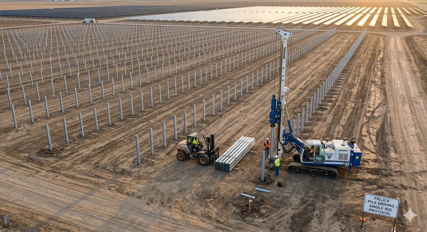
How does staging and material delivery optimize solar pile driving rates?
- Forklift staging drops exact pile counts adjacent to driven coordinates, orienting flanges to minimize rig handling cycles.
- Site demarcation establishes exclusion zones between rough-terrain forklifts and active hydraulic rigs to prevent equipment bottlenecks.
- Immediate real-time quality control checks directly behind the rig confirm plumb and reveal tolerances before moving past the active array block.
Complete Course on
Piping Engineering
Check Now
Key Features
- 125+ Hours Content
- 500+ Recorded Lectures
- 20+ Years Exp.
- Lifetime Access
Coverage
- Codes & Standards
- Layouts & Design
- Material Eng.
- Stress Analysis
