Soil Bearing Capacity Calculations for Safe Structural Foundation Design
In my two decades of industrial piping and structural engineering design, I have observed that foundation failures rarely originate from inadequate concrete mix designs; instead, they stem from improper geotechnical evaluation of soil bearing capacity. When designing heavy pipe racks, process vessels, and dynamic equipment supports, establishing accurate SBC values is mandatory to prevent differential settlement.
The interaction between structural loads and subgrade resistance dictates the sizing of shallow and deep foundations. By understanding shear strength parameters like cohesion and internal friction angle, engineers can optimize foundation footprints and ensure structural integrity across varied soil profiles.
Key Engineering Takeaways
- Low SBC soils require significantly larger footing surface areas to distribute vertical loads safely.
- Shear strength parameters (c and phi) directly drive ultimate bearing capacity formulations.
- A fivefold increase in SBC drastically reduces concrete volume and reinforcement requirements.
- Adherence to ASCE 7 minimum requirements prevents catastrophic foundation rocking and tilting.
Soil Bearing Capacity Fundamentals and Mathematical Formulation
When evaluating subgrade response under heavy industrial loads, I always begin with Terzaghi’s bearing capacity theory. For a continuous strip footing, the ultimate bearing capacity (q_u) is expressed through three distinct components: cohesion, surcharge pressure, and soil unit weight.
The generalized bearing capacity equation is formulated as:
Where c represents soil cohesion, q is the effective overburden surcharge pressure at the footing base level, gamma is the effective unit weight of the soil, B is the footing width, and N_c, N_q, N_gamma are dimensionless bearing capacity factors dependent strictly on the internal friction angle (phi).
Comparative Subgrade Analysis Across Soil Conditions
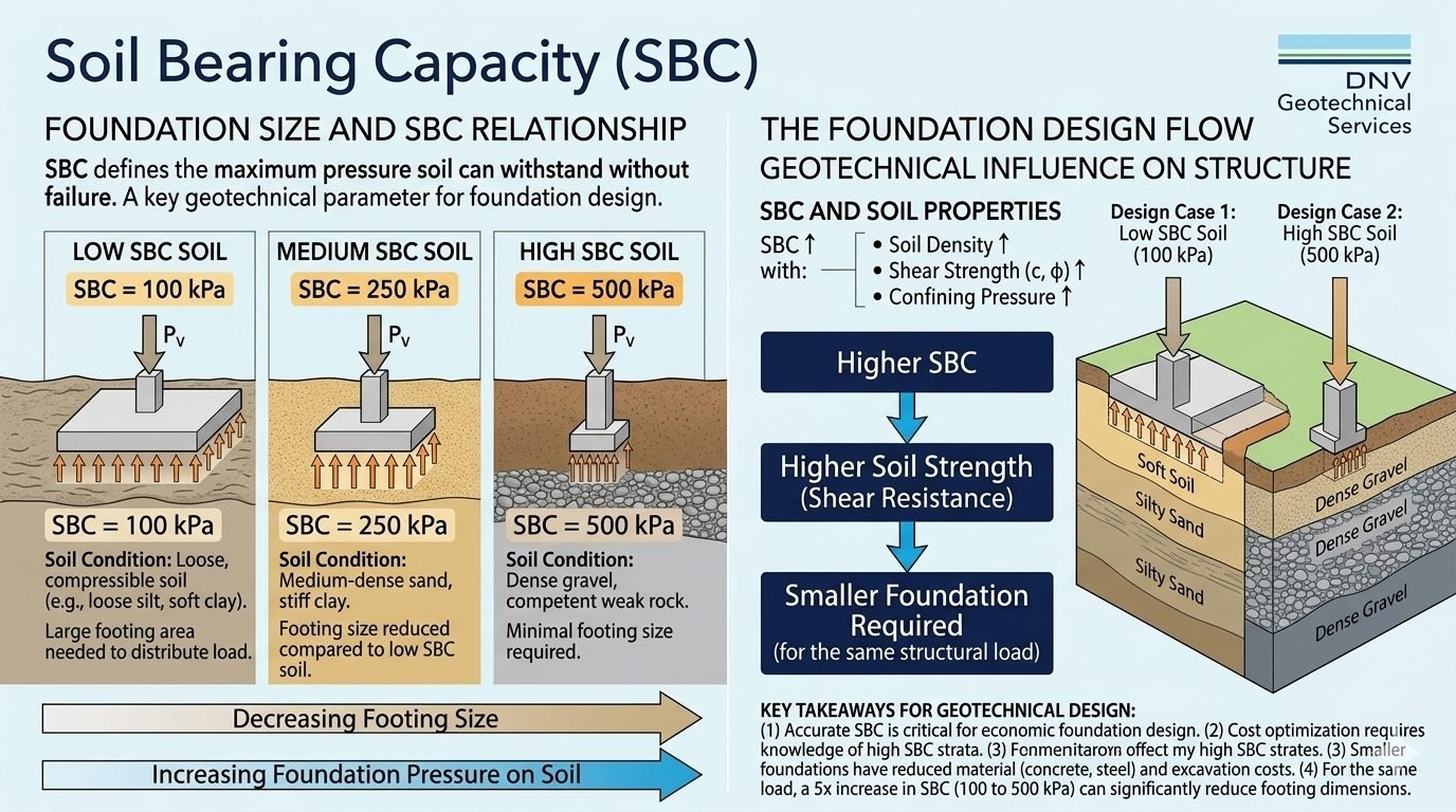
To illustrate how subgrade variability impacts structural design, consider three distinct soil conditions subjected to an identical applied vertical load (P_v):
- Low SBC Soil (100 kPa): Characterized by loose silts or soft clays with low cohesion and minimal internal friction. This condition demands an expansive footing area to keep applied contact pressure beneath the allowable threshold.
- Medium SBC Soil (250 kPa): Comprising medium-dense sand or stiff clay. This profile permits moderate footing dimensions, balancing excavation depth and structural concrete volume efficiently.
- High SBC Soil (500 kPa): Represented by dense gravel deposits or competent weak rock. High shear resistance allows minimal footing footprints while supporting substantial structural dead and live loads.
Geotechnical Safety Warning
Never apply presumptive bearing capacity values from local building codes without corroborating standard penetration test (SPT) N-values or cone penetration test (CPT) data.
Ignoring groundwater table fluctuations can reduce effective unit weight by nearly 50%, triggering catastrophic loss of bearing resistance and sudden differential settlement.
Allowable Bearing Pressure and Factor of Safety
Structural foundation sizing relies strictly on allowable bearing capacity (q_a), derived by dividing the ultimate bearing capacity (q_u) by a suitable factor of safety (FS). According to ASTM standards, a minimum factor of safety of 3.0 is standard for static dead and live loads, while transient wind and seismic combinations permit an FS of 2.0.
Net allowable bearing pressure (q_na) subtracts the overburden pressure of the excavated soil from the gross allowable pressure:
Where q_0 represents the initial overburden pressure at foundation depth. Ensuring net pressure calculations are exact prevents overestimating subgrade capacity in deep excavation zones.
Settlement Criteria and Elastic Deformation Limits
In my engineering practice, allowable bearing capacity is frequently governed by tolerable settlement rather than gross shear failure. Total settlement comprises immediate elastic settlement, primary consolidation settlement, and secondary creep.
For granular soils, elastic settlement is calculated using Schmertmann’s strain influence factor method or Janbu’s modulus approach. For cohesive soils, primary consolidation settlement is evaluated using void ratio changes and compression indices (C_c) tested per ASTM D2435.
Engineering Advantages
- High bearing capacity subgrades (<500 kPa) minimize concrete volume and steel reinforcement requirements.
- Shallow foundation construction avoids expensive deep piling and excavation shoring systems.
- Predictable stress distribution simplifies structural load transfer modeling for finite element software.
- Compliance with ASCE standards ensures long-term structural stability against overturning and sliding.
- Rapid installation schedules reduce overall capital expenditure on industrial plant construction projects.
Engineering Disadvantages
- Low SBC soils (<100 kPa) demand excessively large footing areas, causing boundary clash issues.
- Vulnerability to differential settlement when soil strata vary across a single equipment skid footprint.
- Groundwater table fluctuations can drastically degrade allowable bearing pressure without drainage mitigations.
- Susceptibility to frost heave and moisture-induced volume changes in expansive clay formations.
- Extensive geotechnical subsurface exploration is mandatory to prevent localized subgrade failure surprises.
Heavy Process Plant Pipe Racks
Interconnected piping networks impose massive vertical dead loads combined with thermal expansion friction forces. Accurate SBC evaluation ensures individual column footings do not experience excessive differential movement that could overstress carbon steel piping.
Designers utilize soil bearing analysis to size spread footings effectively on dense gravel formations while avoiding costly deep pile foundations.
Vertical Distillation Column Foundations
Tall fractionating columns experience severe overturning moments from high wind and seismic lateral loads. The eccentricity of resultant foundation pressures requires high subgrade bearing capacity to prevent edge uplift and base rotation.
Engineers apply rigorous safety factors per ASCE 7 to octagonal or circular mat foundations resting on competent rock strata.
Reciprocating Compressor Skids
Dynamic machinery generates high-frequency vibratory forces that propagate through subsoil layers. Low bearing capacity soils risk resonant amplification and severe foundation fatigue failure if dynamic soil-structure interaction is ignored.
Massive concrete block foundations are engineered to maintain safe soil bearing pressures while dampening operational vibrations within allowable limits.
Tank Farm Storage Bunds
Large atmospheric crude oil storage tanks exert uniform surcharge pressures across extensive ring-wall foundations. Soft subgrade soils demand ground improvement techniques such as vibro-compacted stone columns to increase SBC before tank hydrostatic testing.
Proper bearing capacity analysis prevents catastrophic bearing shear failure during initial filling cycles.
Soil Bearing Capacity Parameters and Geotechnical Foundation Sizing Reference
To establish safe foundation sizing under varied geotechnical conditions, civil engineers must evaluate the precise empirical correlation between soil bearing capacity (SBC), shear strength parameters, and allowable foundation pressures. When reviewing allowable geotechnical limits per ASTM D1587 and ISO 14688 standards, the relationship between soil density, cohesion, and friction angle dictates the required contact area for shallow spread footings.
The comprehensive data layout below synthesizes key geotechnical parameters across low, medium, and high soil bearing capacity profiles subjected to identical vertical structural loads. By analyzing these reference values, project teams can optimize concrete volume and reinforcement steel specifications without violating allowable settlement tolerances defined in ASCE 7 design minimums.
| Soil Classification & Condition | Allowable SBC (kPa) | Cohesion (c) & Friction (phi) | Relative Footing Area (Pv = 2000 kN) | Governing Design Standard |
|---|---|---|---|---|
| Loose Silt / Soft Clay (Low SBC) | 100 kPa | c = 15 kPa, phi = 12 deg | 20.0 m2 (Large Footing) | ASTM D2166 (Unconfined Compressive) |
| Medium-Dense Sand / Stiff Clay (Medium SBC) | 250 kPa | c = 30 kPa, phi = 28 deg | 8.0 m2 (Moderate Footing) | ASTM D1586 (Standard Penetration) |
| Dense Gravel / Competent Rock (High SBC) | 500 kPa | c = 50 kPa, phi = 38 deg | 4.0 m2 (Minimal Footing) | ISO 22476-3 (Pressuremeter) |
Key Takeaway: Tripling or quintupling the allowable soil bearing capacity exponentially decreases the required concrete footprint for identical superstructure loading, directly optimizing project material economics.
Technical Mapping & Specifications Matrix
Advanced structural engineering design workflows rely on standardized semantic entities to classify geotechnical performance metrics. This mapping matrix breaks down the fundamental structural variables, physical parameters, and governing industry specifications required to accurately compute soil bearing capacity without exceeding allowable settlement thresholds.
By integrating these computational entities into finite element packages and spreadsheet models, engineers ensure full compliance with international safety protocols. Every parameter links directly to standardized testing procedures outlined by global geotechnical authorities.
| Entity Term | Structural Acronym | Physical Parameter & Units | Governing Code Reference |
|---|---|---|---|
| Ultimate Bearing Capacity | qu | Maximum shear resistance stress (kPa) | ASCE 7 Chapter 18 |
| Allowable Bearing Capacity | qa | Design pressure with safety factor (kPa) | ASTM D6572 Guidelines |
| Soil Cohesion Factor | c | Shear intercept strength parameter (kPa) | ASTM D3080 Shear Box |
| Internal Friction Angle | phi | Granular interlock resistance (degrees) | ISO 17892-9 Triaxial |
Implementation Note: Always verify that site-specific laboratory triaxial test results align with empirical presumptive values before finalizing spread footing sizing calculations.
Site Verification Checklist for Soil Bearing Capacity
Executing foundation construction requires rigorous field validation to ensure actual subgrade conditions match geotechnical report projections. Failure to verify field soil parameters can result in catastrophic differential settlement or bearing shear failure. Use this structured verification checklist prior to pouring blinding concrete or setting foundation formwork.
Geotechnical Site Inspection Verification Protocol
- Subgrade Compaction Test: Verify that backfill or in-situ subgrade compaction reaches a minimum of 95 percent Modified Proctor density per ASTM D1557 standards.
- Groundwater Level Control: Confirm groundwater table is maintained at least 1.0 meter below the footing excavation invert to prevent pore pressure buildup and bearing capacity reduction.
- In-Situ Shear Strength Audit: Conduct dynamic cone penetrometer or pocket vane shear tests to validate that cohesive or granular soil strength meets design assumptions.
- Excavation Bottom Integrity: Inspect foundation pit base for loose debris, sloughing material, or soft pockets, ensuring firm, undisturbed native strata.
- Proof Rolling Validation: Execute a heavy pneumatic tire proof roll on cohesive subgrades to detect localized soft spots and rutting potential.
Validation Requirement: Sign-off from the geotechnical engineer of record is mandatory on each checklist item before structural reinforcement placement can commence.
Field Case Study: Real-World Application
A heavy industrial manufacturing plant expansion required the placement of a major compressor foundation package carrying a total vertical load of 12,000 kN across varying geotechnical strata. The project site encountered soft alluvial silt layers overlying competent dense gravel, posing significant differential settlement risks.
Geotechnical Problem Encountered
Preliminary soil borings revealed low soil bearing capacity conditions (SBC = 100 kPa) extending 3.5 meters below grade across 60 percent of the compressor footprint, threatening severe structural tilt.
- Initial spread footing sizing calculations demanded an unmanageably massive 120 square meter concrete raft.
- High compressibility of the upper saturated silt layer threatened excessive immediate and long-term consolidation settlement.
- Dynamic cyclic loading from reciprocating compressors risked triggering liquefaction and shear failure in loose soil pockets.
- Excavation and replacement of the soft stratum proved economically unfeasible due to deep overburden depths.
Engineering Solution and Outcome
By redesigning the foundation system to transfer loads through vibro-replacement stone columns down to the high-bearing gravel strata (SBC = 500 kPa), the project team achieved complete stability and significant cost savings.
- Effective composite soil bearing capacity increased from 100 kPa to 350 kPa across the entire plant footprint.
- Required footing plan area was reduced by 71 percent, saving over 450 cubic meters of structural reinforced concrete.
- Differential settlement was successfully restricted to less than 4 millimeters, well within compressor manufacturer tolerances.
- Full compliance was verified against ASCE 7 and ASTM D1586 geotechnical performance criteria.
Final Recommendation: When encountering variable soil bearing capacity profiles on industrial sites, deep ground improvement techniques should always be evaluated alongside traditional deep foundation alternatives to optimize material economy and schedule delivery.
Frequently Asked Engineering Questions
How does soil bearing capacity directly dictate shallow foundation sizing?
What differentiates low soil bearing capacity from high bearing capacity conditions?
- Loose silts and soft clays exhibit low capacities around 100 kPa requiring wide footprints.
- Dense gravels and competent rocks reach 500 kPa or higher, enabling minimal footing sizing.
- Shear strength parameters c and phi dictate overall load resistance behavior.
Why is soil stratification critical when evaluating foundation performance?
- Stiff surface crusts can mask compressible soft clay layers situated deeper below the footing.
- Punching shear failures occur when high loads overstress weak underlying strata.
- Geotechnical borehole logs must span the entire depth of the active stress zone.
How do groundwater fluctuations impact allowable bearing pressure?
- Buoyant unit weight calculations cut effective overburden pressure in half for submerged soils.
- Capillary fringe effects and seasonal table rises require strict factor of safety margins.
- Drainage mitigation strategies protect subgrade integrity from moisture softening.
What engineering standards govern allowable bearing pressure calculations?
- Terzaghi and Meyerhof bearing capacity theories form the analytical backbone of calculations.
- ISO 19902 and national building codes mandate minimum safety factors for foundation design.
- In-situ testing correlations ensure theoretical models match real site conditions.
Field Recommendation
In my professional practice reviewing industrial plant foundations, I always advise multidisciplinary teams to prioritize exhaustive geotechnical data acquisition before freezing structural sizing layouts. Making conservative assumptions without site verification leads to severe economic penalties or catastrophic differential settlements.
- If subgrade exploration reveals variable soft clay pockets beneath a heavy process compressor skid, reject shallow spread footings immediately and specify driven steel piles to transfer loads to competent bearing strata.
- When encountering marginal soils with an allowable bearing capacity near 100 kPa, mandate mechanical soil densification or lime stabilization before pouring concrete to avoid excessive footing footprints that crowd underground utility corridors.
- Always incorporate a minimum safety factor of 3.0 against general shear failure when analyzing static equipment foundations subject to high eccentric moments and dynamic vibrations.
- If seasonal groundwater table fluctuations are anticipated within the active stress zone of shallow foundations, enforce a composite waterproofing and subgrade drainage design to prevent long-term capacity degradation.
Complete Course on
Piping Engineering
Check Now
Key Features
- 125+ Hours Content
- 500+ Recorded Lectures
- 20+ Years Exp.
- Lifetime Access
Coverage
- Codes & Standards
- Layouts & Design
- Material Eng.
- Stress Analysis
