Guidelines for Slurry Piping System Design
Key Takeaways
- Velocity Optimization: Operating 0.3 to 0.5 m/s above the critical settling velocity is vital to prevent bed formation without accelerating pipe erosion.
- Rheological Mastery: Distinguishing between homogeneous and heterogeneous flow regimes dictates the selection of pump types and pressure drop models.
- Material Resilience: Integrating sacrificial wall thickness or elastomeric liners is mandatory for handling high-concentration abrasive solids.
What is Slurry Piping System Design?
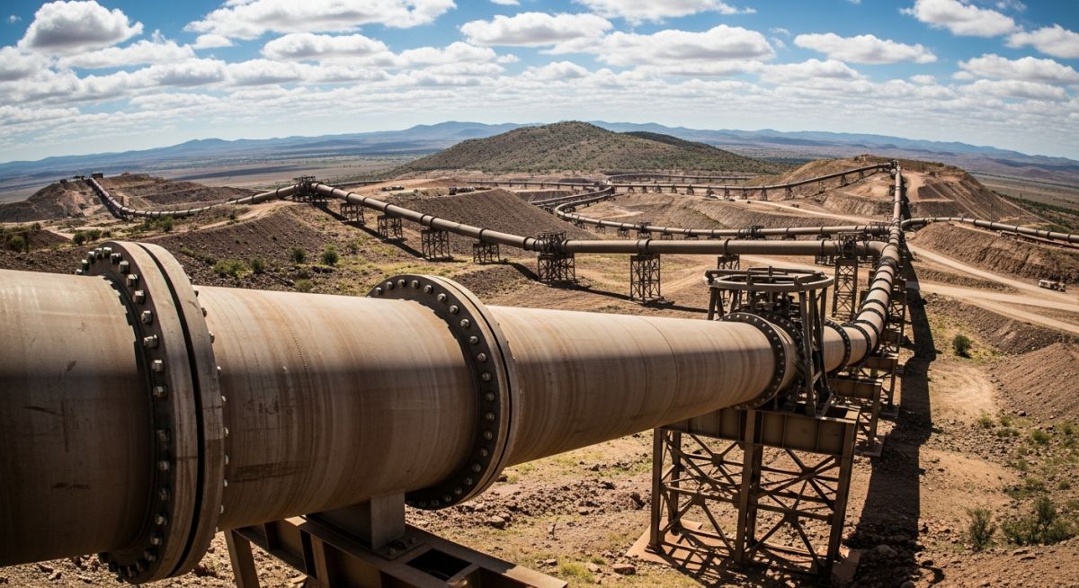
Slurry Piping System Design is the specialized engineering discipline of transporting solid particles suspended in a liquid carrier. It requires calculating critical settling velocity to prevent sedimentation, selecting abrasion-resistant materials like HDPE or rubber-lined steel, and applying rheological models (e.g., Bingham Plastic) to maintain stable hydraulic transport and operational efficiency.
Founder’s Insight
“In my two decades of plant design, I’ve seen more slurry lines fail due to over-conservative sizing than under-sizing. If your velocity is too high, you’ll eat through a scheduled 10-year pipe life in 18 months. Precision in Slurry Piping System Design is the only way to balance CAPEX with sustainable OPEX.”
— Atul Singla
Table of Contents
- Fundamental Principles of Slurry Piping System Design
- Key Factors Affecting Slurry Behaviour and Rheology
- Calculations for Slurry Piping System Design: Sizing & Pressure Drop
- Material Selection and Slurry Piping System Design Considerations
- Operational Challenges in Long-Distance Slurry Pipelines
- Real-World Examples of Slurry Piping System Design
Complete Course on
Piping Engineering
Check Now
Key Features
- 125+ Hours Content
- 500+ Recorded Lectures
- 20+ Years Exp.
- Lifetime Access
Coverage
- Codes & Standards
- Layouts & Design
- Material Eng.
- Stress Analysis
Engineering Knowledge Check
Question 1 of 5What is the primary risk of operating a Slurry Piping System Design below the critical settling velocity?
Fundamental Principles of Slurry Piping System Design
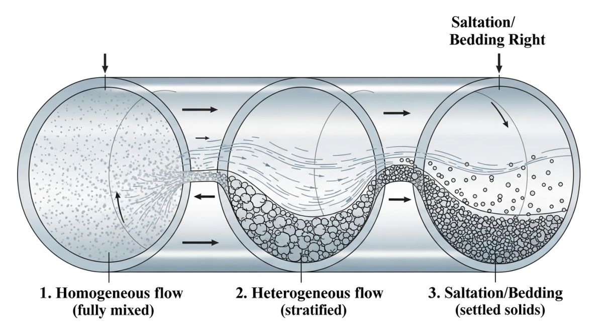
The core objective of Slurry Piping System Design is to transport solids at a concentration and velocity that prevents the formation of a stationary bed while minimizing mechanical wear. Unlike clear water systems, slurry hydraulics are governed by the interaction between the carrier fluid and the solid particles. This interaction creates specific flow regimes. In a homogeneous slurry, the particles are so fine or the turbulence so high that the mixture behaves like a single-phase fluid with an increased density and viscosity. Conversely, heterogeneous slurries exhibit a distinct concentration gradient, where heavier particles gravitate toward the bottom of the pipe, necessitating higher velocities to maintain suspension.
Engineering professionals must adhere to established codes such as ASME B31.4 (Pipeline Transportation Systems for Liquids and Slurries) to ensure structural integrity and safety. The design process begins with a comprehensive analysis of the solid properties, including d50 particle size, specific gravity, and the chemical compatibility of the carrier liquid. Neglecting these fundamentals often leads to premature failure via “sanding out” or localized erosion at fittings.
Key Factors Affecting Slurry Behaviour and Rheology
In Slurry Piping System Design, rheology is the study of how the mixture deforms under stress. Most mineral slurries at high concentrations exhibit non-Newtonian behavior, specifically acting as Bingham Plastics or Pseudoplastics. A Bingham Plastic requires a specific “yield stress” to be exceeded before any movement occurs. This is critical for pump selection, as the motor must provide enough torque to “break” the static slurry and initiate flow after a shutdown.
The behavior of the slurry is further influenced by the Solid Concentration by Volume (Cv). As Cv increases, the viscosity rises exponentially, leading to higher frictional pressure drops. However, higher concentrations can sometimes be beneficial by damping turbulence and reducing the impact velocity of abrasive particles against the pipe wall. The designer’s challenge is finding the “sweet spot” where the system remains stable without requiring excessive pumping power.
Another vital factor is particle shape. Angular, sharp-edged particles in mining tailings cause significantly higher erosion rates than rounded river sands. When performing Slurry Piping System Design, the “Miller Number” is often used to quantify the abrasivity of the slurry, directly influencing the choice of pipe material and the allowance for sacrificial wall thickness.
Calculations for Slurry Piping System Design: Sizing & Pressure Drop
Precision in Slurry Piping System Design hinges on the accurate determination of the Critical Settling Velocity (VL). Operating below this threshold results in solids forming a stationary or sliding bed, which reduces the effective cross-sectional area and causes a catastrophic rise in pressure. The Durand Equation remains a cornerstone for estimating this limit, though modern CFD (Computational Fluid Dynamics) modeling is increasingly used for complex geometries. Engineers must also calculate the Volume flow rate (Q = V × A), ensuring the design velocity stays 0.3 to 0.5 m/s above VL to account for transient fluctuations in pump performance or slurry density.
Pressure drop calculations for slurries differ from water due to the “solids effect.” The total friction loss is the sum of the fluid friction and the additional friction caused by the solids interacting with the pipe wall. For long-distance transport, even a 5% error in head loss calculation can result in requiring an additional booster station, significantly impacting the project’s CAPEX. References to ISO 14837 (Mechanical Vibration) and ASME B31.11 (Slurry Transportation Piping Systems) provide the necessary safety factors for these hydraulic calculations.
| Design Parameter | Homogeneous Slurry | Heterogeneous Slurry |
|---|---|---|
| Particle Size | Typically < 30-50 microns | Typically > 50-100 microns |
| Velocity Sensitivity | Low; behaves like heavy liquid | High; must exceed Critical Velocity |
| Pressure Drop Model | Modified Darcy-Weisbach | Durand or Wasp Equations |
| Wear Pattern | Uniform circumferential wear | Localized wear at 6 o'clock position |
Material Selection and Slurry Piping System Design Considerations
Material selection is the primary defense against erosion in Slurry Piping System Design. While carbon steel is the structural baseline, its resistance to abrasive slurry is poor without modification. Engineers often specify API 5L grade steel with a significant corrosion/erosion allowance, or transition to internal linings. Rubber-lined steel is the industry standard for mining, as the elastomer absorbs the kinetic energy of impacting particles, bouncing them back into the flow stream rather than allowing them to gouge the surface.
For lower pressure or smaller diameter lines, HDPE (High-Density Polyethylene) is a preferred choice due to its inherent lubricity and resistance to pitting. However, thermal expansion must be carefully managed in HDPE systems, as the expansion coefficient is significantly higher than that of steel. In high-temperature slurry applications, such as oil sands processing, specialized ceramic-lined components or hardened alloys like Chrome-Moly steel are required to maintain system integrity over the 2026 operational lifecycle.
Slurry Design Velocity Estimator
Calculate the recommended operational velocity based on the estimated critical settling velocity (VL) to ensure stable Slurry Piping System Design.
Calculated via Durand or Wasp methods.
Standard industry range: 0.3 – 0.5 m/s.
Technical Case Study: Copper Concentrator Tailings
Project Scope
12km transport of abrasive copper tailings (d50 = 75 microns) at 45% solids by weight.
Primary Challenge
Unpredictable power outages leading to line sedimentation and subsequent startup blockages.
Design Solution
Implementation of a 1.5% gradient slope and high-torque variable frequency drives (VFDs).
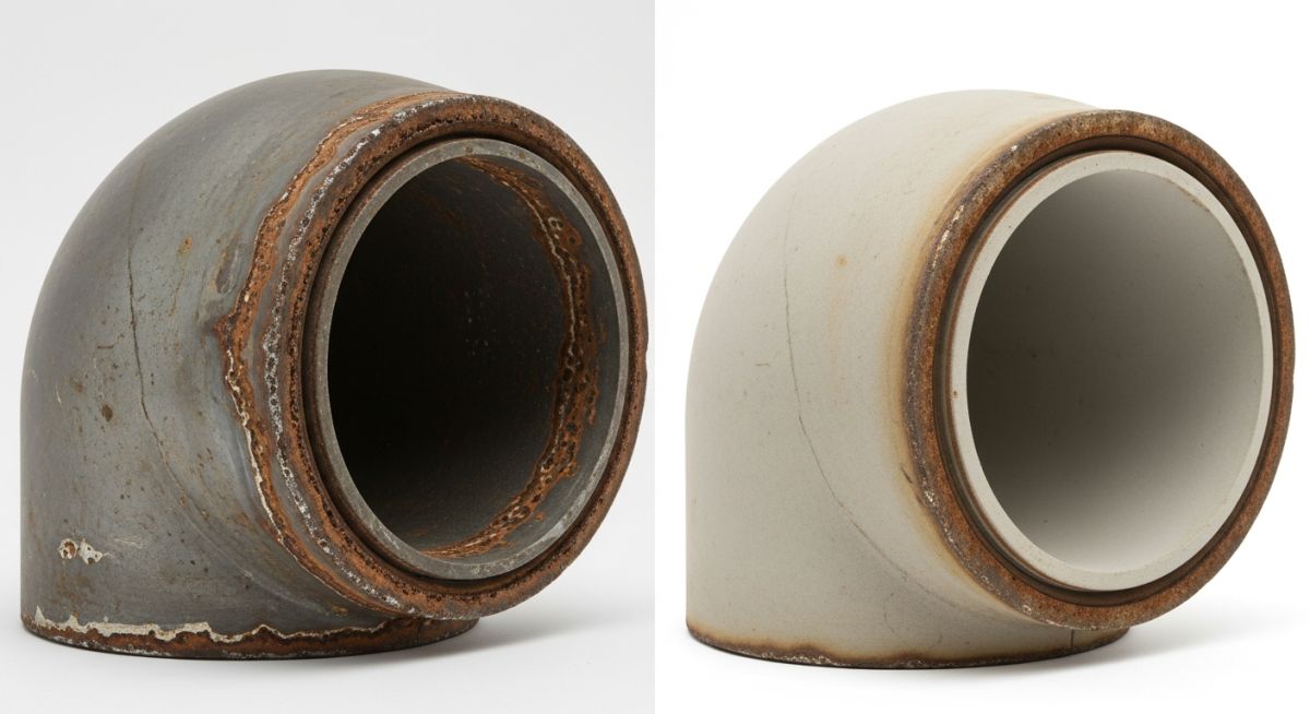
Engineering Intervention
The initial Slurry Piping System Design utilized standard schedule 80 carbon steel. Within 14 months, the bottom "6 o'clock" position of the pipe showed a 40% loss in wall thickness due to heterogeneous flow abrasion. The system was retrofitted in 2026 with 10mm natural rubber lining and a revised pump curve targeting a design velocity of 3.2 m/s (0.5 m/s above calculated VL).
Measurable Results:
- Extended Lifecycle: Projected pipe life increased from 2.5 years to 12 years post-lining.
- Energy Efficiency: Optimized velocity reduced specific power consumption by 12% compared to the previous over-velocity operation.
- Zero Blockages: The high-torque startup sequence successfully cleared the line after three separate emergency power trips.
Expert Insights: Lessons from 20 years in the field
The "Stop-Start" Reality
In Slurry Piping System Design, your system is only as good as its ability to restart. Always design for the "worst-case" settled bed condition. Ensure your pump motors have sufficient starting torque to overcome the yield stress of a compacted solid bed after an emergency shutdown.
Inclination Limits
Avoid vertical or steeply inclined sections exceeding 15 degrees whenever possible. If unavoidable, increase the design velocity by 15-20% in those specific segments to prevent "slugging" or back-flow of heavier particles during transient states.
Instrument Protection
Never use standard pressure gauges with stagnant sensing lines. Use chemical seals or "diaphragm seals" with flush ports. In a slurry line, a standard sensing line will plug with solids within minutes, rendering your control system blind.
The 6 O'Clock Rule
For unlined pipelines, implement a periodic pipe rotation program (e.g., 90-degree rotation every 2 years). This distributes the localized "6 o'clock" erosion across the entire circumference, effectively quadrupling the pipe's service life.
References & Standards
To ensure compliance with global safety and engineering benchmarks for 2026, refer to the following official resources:
- ▶ ASME B31.4: Pipeline Transportation Systems for Liquids and Slurries.
- ▶ API 5L: Specification for Line Pipe - Critical for material grade selection.
- ▶ ISO 14837: Mechanical Vibration and Slurry Transport Standards.
- ▶ ASME B31.11: Detailed Slurry Transportation Piping Systems Guide (Historical Reference for B31.4).
EPCLand YouTube Channel
2,500+ Videos • Daily Updates


