
Sight Glasses for Oil and Gas: The Definitive 2026 Engineering Guide
The safe and efficient operation of petrochemical facilities hinges on accurate fluid level monitoring. Sight glasses for oil and gas applications are not mere windows; they are critical safety components governed by strict codes like ASME B31.3 and API 650. This guide provides process, mechanical, and instrumentation engineers with the definitive criteria for selection, material compatibility, P-T rating validation, and regulatory compliance to maximize service life and prevent catastrophic failure.
What is an Industrial Sight Glass?
An industrial sight glass is a visual indicator or level gauge installed on a pressurized vessel, tank, or piping system that allows operators to safely observe the fluid level or flow status inside. These devices are custom-engineered assemblies consisting of a metallic body, a transparent viewing element (usually borosilicate or aluminosilicate glass), and highly specific gaskets, all rated to withstand the design pressure, temperature, and corrosive nature of the contained hydrocarbon fluid.
Sight Glass Engineering Quiz: Test Your Knowledge
Complete Course on
Piping Engineering
Check Now
Key Features
- 125+ Hours Content
- 500+ Recorded Lectures
- 20+ Years Exp.
- Lifetime Access
Coverage
- Codes & Standards
- Layouts & Design
- Material Eng.
- Stress Analysis
What is a Sight Glass? (Process Observation Fundamentals)
At its core, a sight glass—sometimes referred to as an **industrial sight flow indicator** when used in a piping run—is a direct-reading instrument. Unlike electronic sensors, it provides real-time, unambiguous visual feedback to the operator. This fundamental simplicity makes it indispensable in complex hydrocarbon processing plants where level, flow, or fluid condition must be verified independently of control systems. These units consist of a metallic body (often carbon steel or stainless steel), a transparent window (the glass element), and a gasket/sealing system designed to hold the process fluid under pressure.
The design must withstand the rigors of service, including high-cycling temperatures and pressures. A failure of this instrument can lead to dangerous releases or misreading of critical process variables, highlighting the non-negotiable need for robust engineering and adherence to pressure vessel and piping codes.
Operational Criticality: Importance of Sight Glasses in Process Safety
Sight glasses are often a mandated component in safety integrity systems. In the oil and gas sector, their primary importance stems from:
- Redundancy: They serve as a crucial local indicator to cross-check readings from remote or electronic transmitters, preventing catastrophic overfilling or underfilling of vessels.
- Interface Detection: In separators, they are often the most reliable way to visually confirm the level and quality of the liquid-liquid interface (e.g., oil-water separation).
- Process Diagnostics: Operators use them to observe foaming, boiling, color changes, and sediment build-up, all vital signs of a process upset.
- Start-up/Shutdown Procedures: Manual monitoring during critical phases ensures levels are within safe operating limits before automated controls are engaged.
Classification: Primary Types of Industrial Sight Glasses
The application dictates the type of sight glass selected. The core decision revolves around visibility requirements and the safety margin necessary for the process fluid.
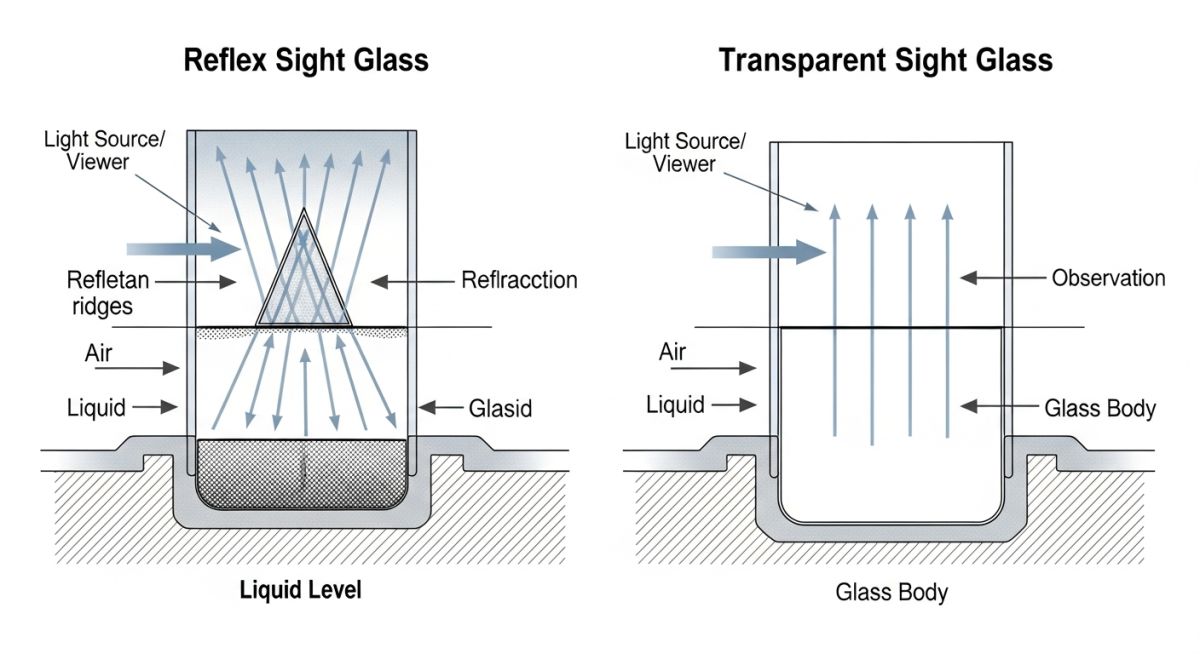
Transparent Sight Glasses: Best for Interface Observation
These units use two flat pieces of glass (front and back) clamped to the gauge body, allowing light to pass directly through the process fluid. They are mandatory when the operator needs a direct view of the fluid itself, particularly for color verification or when observing the level of two immiscible liquids (e.g., water and oil) to determine the interface level.
Reflex Sight Glasses: High-Contrast Liquid Level Detection
The **reflex level gauge vs transparent** debate often centers on the need for contrast. Reflex glasses use a single, specialized glass with prismatic grooves cut into the surface facing the liquid. The liquid-filled section appears dark (as light is absorbed or refracted away), while the vapor-filled section appears bright (as light is reflected back to the viewer).
- Advantage: Provides an exceptionally clear, high-contrast, 'two-color' reading for a single liquid level.
- Disadvantage: Cannot be used to observe fluid color, clarity, or liquid-liquid interfaces.
Magnetic Sight Glasses: The Sealless Safety Alternative
The Magnetic Level Indicator (MLI) is a sealless gauge used for high-risk, high-pressure, or toxic services (e.g., H2S, Ammonia). It replaces the pressure-retaining glass with a sealed metallic chamber. Inside the chamber, a float containing magnets tracks the liquid level. Outside, a set of bi-color flags or shutters (magnetic followers) flips as the float passes, providing a safe, clear visual indication without glass under pressure.
Material Selection: Glass, Gaskets, and Metallurgy
The long-term reliability of a sight glass is entirely dependent on its materials of construction.
- Glass Material:
Borosilicate Glass (low thermal expansion, high thermal shock resistance) is the industry standard for most applications. For extreme chemical resistance or very high pressures, **Aluminosilicate Glass** may be specified. - Gaskets:
Sight glass gasket selection is critical. Materials must be chemically compatible (e.g., Graphite for high temperature, PTFE for strong acids/bases) and resilient to prevent leaks. The correct torque specification must be followed to prevent glass breakage. - Body Metallurgy:
The housing is typically Carbon Steel (A105/A216 WCB) or Stainless Steel (304/316). For sour service, the body material must comply with the strict requirements of **NACE MR0175/ISO 15156** to prevent Sulfide Stress Cracking (SSC).
EPCLand YouTube Channel
2,500+ Videos • Daily Updates
Engineering Selection Criteria (The Specification Matrix)
Selecting the correct sight glass moves beyond simple level observation; it is a critical exercise in fitness-for-service evaluation. A matrix of process, mechanical, and regulatory factors must be considered to prevent premature failure.
Fluid Compatibility & NACE Compliance
Chemical compatibility is paramount. The glass and the **sight glass gasket selection** must not degrade, cloud, or become brittle from exposure to the process fluid. For corrosive services, metallic bodies may need internal cladding or specialized alloys. Furthermore, any metallic component exposed to sour service (H₂S content) must comply strictly with **NACE MR0175** requirements to prevent catastrophic material failure.
Critical Pressure-Temperature (P-T) Ratings
The P-T rating is the maximum allowable working pressure (MAWP) at a given operating temperature. Glass strength degrades significantly as temperature increases. It is crucial to use manufacturer P-T charts, ensuring that the selected glass thickness and body metallurgy can safely contain the maximum process conditions, with an appropriate safety factor.
Thermal Shock & Impact Resistance
Thermal shock occurs when a glass component is exposed to a rapid change in temperature (e.g., cold liquid introduced into a hot vessel). Borosilicate glass offers excellent thermal shock resistance. Mechanical impact from handling, maintenance tools, or external debris necessitates the use of heavy-duty protectors (e.g., mica shields or metallic covers) for additional safety.
Regulatory Standards (ASME VIII, API 650)
A sight glass is considered a pressure retaining component. Its design must comply with:
- ASME B31.3 (Process Piping): For sight flow indicators in piping.
- ASME Boiler and Pressure Vessel Code (ASME VIII Div 1): For installations on pressure vessels, which sets rules for minimum wall thickness and material integrity.
- API 650/API 620: Relevant for storage tank nozzles and external attachment points.
How to Specify a Sight Glass: Data Sheet Essentials
Proper specification prevents procurement errors and ensures safety. The engineering data sheet must include specific parameters.
| Fluid Temperature (°C) | Max Pressure (Bar) - Reflex | Max Pressure (Bar) - Transparent (Glass Gauge) | Glass Type & Compatibility |
|---|---|---|---|
| 20 | 60 Bar | 40 Bar | Borosilicate (High) |
| 100 | 45 Bar | 30 Bar | Borosilicate (Medium) |
| 300 | 15 Bar | 10 Bar | Borosilicate (Low) |
Stress Calculation in Sight Glass Elements
The pressure containment capability of the sight glass is fundamentally limited by the stress on the glass and the body's clamping forces. The maximum circumferential stress (hoop stress) in a cylindrical section can be approximated using the thin-walled pressure vessel formula, adapted for the gauge body:
σH ≈ P × D / (2 × t)
Where: σH is Hoop Stress (Pa), P is Internal Pressure (Pa), D is Inner Diameter of the Glass/Body (m), and t is Wall Thickness (m).
For the glass elements themselves, complex stress analysis involving plate bending theory and thermal gradient stress (not shown) is required to certify the MAWP.
Industry Applications: From Upstream to Downstream
HP/HT Separators and Storage Vessels
Separators (2-phase, 3-phase) use sight glasses to confirm both the total liquid level and the interface level, often requiring a Transparent type. Storage tanks utilize them to verify inventory levels, typically using a more robust, low-pressure design like the tubular or armored tubular gauges.
Piping Systems & Flow Indication
Sight flow indicators in piping are used to confirm flow (e.g., cooling water, lubrication oil returns) or to visually inspect the fluid for color, turbidity, or the presence of gas bubbles.
Subsea and Offshore Harsh Environments
Offshore installations require materials highly resistant to saltwater corrosion (often Monel or Duplex Stainless Steel bodies) and exceptional resistance to vibration. Due to safety concerns and maintenance difficulty, Magnetic Level Indicators (MLIs) are increasingly preferred over glass gauges in these environments.
Industrial Sight Glass Thickness Calculator
Estimate the minimum required thickness (t) for a supported rectangular sight glass plate based on internal pressure (P) and a simplified maximum stress calculation.
Typical Borosilicate S ≈ 40-70 MPa.
Calculation Result:
Minimum Required Thickness (t): -- mm
Formula Used: Simplified stress equation for a rectangular plate (Stress = β * P * W2 / t2), rearranged for thickness (t). Assumes simple support and uses a geometric factor (β ≈ 0.75 for L/W > 2). P is converted to MPa.


