Mastering RTK-GPS for Precision Construction and Pile Driving
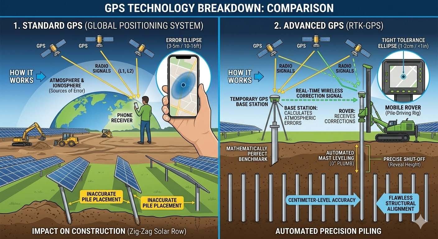
In my two decades of managing large-scale industrial piping and structural projects, I have seen countless hours wasted on re-surveying due to standard GPS drift. When you are driving hundreds of piles for a solar farm or a heavy industrial rack, a 9-meter error ellipse is not just a nuisance; it is a project-killing liability. Standard GPS relies on L1 and L2 frequency bands that are inherently susceptible to ionospheric delays and atmospheric refraction.
I have transitioned my teams to RTK-GPS because it fundamentally changes the site workflow. By deploying a local base station that calculates the difference between known benchmark coordinates and the received satellite signal, we broadcast a correction stream to our rovers. This collapses the error margin from meters down to roughly 1 centimeter. This level of precision is the difference between a perfectly aligned structural grid and a costly, misaligned mess that requires manual rework.
Key Takeaways for Site Engineers
- RTK-GPS eliminates the 9-meter error common in standard consumer-grade GPS receivers.
- Base station proximity is critical; maintain a clear line of sight for the radio link.
- Centimeter-level accuracy enables automated mast leveling and depth control for pile drivers.
- Consistent data streams reduce the need for constant manual stake-out by survey crews.
Technical Mechanics of RTK-GPS Precision
RTK-GPS Implementation: The technical superiority of RTK-GPS lies in its ability to process carrier phase measurements rather than just code-based pseudorange measurements. While standard GPS receivers calculate position based on the time delay of the signal, RTK-GPS systems analyze the phase of the carrier wave itself, which has a much shorter wavelength, allowing for significantly higher resolution.
To achieve this, the base station must be set up over a known survey benchmark. The base station compares the satellite signals it receives against its known, fixed position. It then calculates the atmospheric and ionospheric errors in real-time. These corrections are transmitted via UHF radio or cellular data (NTRIP) to the rover unit mounted on the pile-driving rig. The rover applies these corrections to its own raw satellite data, effectively canceling out the common-mode errors.
When we integrate this into automated pile driving, the rover provides continuous XYZ coordinates to the machine control system. The system uses these coordinates to adjust the mast angle and depth in real-time. The math involves solving the integer ambiguity of the carrier phase, which is the most complex part of the calculation. If the system loses the “fixed” solution, it reverts to a “float” solution, which can have decimeter-level errors. This is why maintaining a clear sky view and a stable radio link is non-negotiable.
From a standards perspective, we look to ASME B30.5 for mobile equipment safety and various ISO 17123 standards for surveying instrumentation. When the pile driver receives the correction, the onboard computer calculates the required hydraulic adjustments to keep the pile within the tolerance specified in the structural drawings. This is not just about speed; it is about ensuring that the structural integrity of the foundation is not compromised by improper pile placement or verticality.
In my experience, the most common failure point is the radio link. If the site has significant topography or heavy steel structures, the UHF signal can be blocked. In these cases, I shift to cellular-based corrections or install repeaters to ensure the rover never loses its “fixed” status. Without that constant stream, the machine control system will pause, causing downtime. Always verify the latency of your correction stream; anything over 1 second can lead to oscillation in the automated control loops.
Advantages & Disadvantages
RTK-GPS Operational Trade-offs: Implementing high-precision positioning systems requires balancing the immediate gains in site productivity against the technical overhead of maintaining a local reference network.
Advantages
- Centimeter-level accuracy for structural alignment.
- Significant reduction in manual stake-out labor.
- Real-time feedback for automated machine control.
- Improved safety by minimizing personnel near heavy equipment.
- Consistent data logging for project quality assurance.
Disadvantages
- High initial capital investment for base/rover kits.
- Requires clear line of sight to satellites.
- Radio link sensitivity to site obstructions.
- Dependency on continuous power for base stations.
- Requires specialized training for site operators.
Real-World Applications
Industry Deployment Scenarios: RTK-GPS is utilized across various heavy civil and industrial sectors to ensure that structural components are placed exactly according to the design model.
Utility-Scale Solar Farm Construction
In solar projects, thousands of piles must be driven with precise spacing to accommodate the racking systems. RTK-GPS allows the pile driver to navigate to each coordinate automatically, ensuring the rows are perfectly straight and the piles are at the correct depth.
Heavy Industrial Foundation Piling
For large-scale industrial plants, foundation piles must be placed with extreme accuracy to support heavy equipment and piping racks. RTK-GPS ensures that the pile cap layout matches the structural steel design, preventing costly field modifications during the erection phase.
Automated Earthmoving and Grading
Beyond piling, RTK-GPS is the backbone of automated grading for site preparation. By controlling the blade height of dozers and graders, the system ensures that the site is leveled to the exact design elevation, which is critical for drainage and structural stability.
In my experience, understanding the fundamental performance gap between standard GNSS and RTK-GPS is the first step toward achieving site-wide precision. Standard GPS relies on a single receiver calculating position based on time-of-flight signals from satellites, which are inherently susceptible to ionospheric delays and orbital ephemeris errors. These variables create a floating error ellipse that is unacceptable for structural piling.
The table below outlines the critical performance differences between standard L1/L2 receivers and RTK-enabled systems. By utilizing a base station to calculate carrier-phase measurements, we effectively cancel out common-mode errors, shifting our tolerance from meters to millimeters. This transition is essential for meeting the stringent requirements of ASCE standards for structural foundation alignment.
| Parameter | Standard GPS | RTK-GPS |
|---|---|---|
| Horizontal Accuracy | 3.0 to 9.0 meters | 10 to 20 millimeters |
| Vertical Accuracy | 5.0 to 15.0 meters | 20 to 30 millimeters |
| Correction Method | None (Standalone) | Wireless Base-to-Rover |
| Signal Processing | Code-based (L1/L2) | Carrier-phase (L1/L2/L5) |
Engineers must note that these values assume a clear sky view and a stable base station setup. Any obstruction, such as heavy equipment or site structures, can lead to cycle slips, which temporarily degrade the RTK solution back to standard GNSS levels until the ambiguity resolution is re-established.
To successfully integrate RTK-GPS into a construction workflow, one must map the interaction between hardware components and the governing signal protocols. The matrix below categorizes the essential entities involved in the RTK chain, from the satellite constellation down to the machine control interface on the pile driver.
Each component plays a specific role in maintaining the integrity of the carrier-phase measurements. By referencing these standards, project managers can ensure that their equipment procurement aligns with the required site tolerances and ISO surveying guidelines for automated machinery.
| Entity | Function | Standard/Protocol |
|---|---|---|
| Base Station | Reference point calculation | RTCM 3.x |
| Rover Receiver | Real-time position correction | NMEA 0183 |
| Data Link | Correction signal transmission | UHF/Cellular |
| Machine Control | Automated mast leveling | CAN Bus |
The synergy between these entities is what allows for the “fixed” solution state, where the rover has successfully resolved the integer ambiguities of the carrier wave. Without this resolution, the system remains in a “float” state, which is insufficient for precision piling operations.
Before initiating any automated piling sequence, I mandate a rigorous site verification process. RTK-GPS is highly sensitive to environmental factors and base station placement. Failure to validate these parameters often results in “drift” or “jump” errors that compromise the entire structural grid.
- 01. Base Station Stability: Ensure the base station is mounted on a survey-grade tripod or a permanent, vibration-free monument. Verify the benchmark coordinates against a known NGS control point.
- 02. Clear Sky View: Confirm that the base station has an unobstructed 360-degree view of the horizon. Any masking above 10 degrees elevation significantly increases the risk of multipath interference.
- 03. Data Link Integrity: Test the UHF radio or cellular modem connection between the base and the rover. Ensure the latency of the correction signal remains below 1 second to prevent stale data errors.
- 04. Calibration Check: Perform a “check-in” on at least three known site control points before starting the machine. The delta between the RTK-reported position and the known coordinate must be within 20mm.
- 05. Firmware Synchronization: Verify that both the base and rover receivers are running the same firmware version to ensure compatibility with the latest RTCM message types.
Once these checks are complete, the operator must confirm the “Fixed” status on the machine control display. Never proceed with automated piling if the system indicates a “Float” or “DGPS” status, as these modes lack the necessary precision for structural foundation work.
Problem: Inaccurate Pile Placement in Solar Farm Construction
A large-scale solar project faced significant delays due to pile misalignment caused by standard GPS drift, resulting in a zig-zagging row pattern that prevented the mounting of solar trackers.
- Cumulative positioning error exceeding 0.5 meters across long rows.
- Manual re-surveying required for every 10th pile, halting production.
- Inconsistent pile depth due to lack of automated mast control.
- High rework costs associated with extracting and re-driving misaligned piles.
Outcome: Centimeter-Level Precision via RTK-GPS Integration
By implementing a dedicated RTK-GPS base station and upgrading the pile-driving rig to an automated machine control system, the project achieved immediate structural alignment success.
- Achieved consistent 15mm horizontal accuracy across the entire site.
- Eliminated the need for manual stake-out, increasing daily pile output by 40%.
- Automated depth control ensured every pile met the required refusal torque.
- Reduced structural rework to near zero, significantly improving project margins.
My recommendation for similar projects is to prioritize the establishment of a robust, site-specific control network before the arrival of heavy machinery. Investing in a high-quality base station setup is the most effective way to guarantee the accuracy required for modern automated construction.
Frequently Asked Engineering Questions
How does RTK-GPS differ from standard consumer-grade GPS?
- Real-time correction data transmitted from a stationary base station.
- Carrier-phase measurement rather than simple code-based positioning.
- Continuous comparison against a known, high-precision benchmark coordinate.
- Elimination of common-mode errors caused by satellite clock drift and orbital variations.
What is the role of the base station in RTK-GPS?
- Generating precise atmospheric and ionospheric correction vectors.
- Broadcasting these corrections via radio or cellular links to the rover.
- Maintaining a stable, fixed location to ensure consistent data integrity.
- Providing the mathematical foundation for centimeter-level spatial accuracy across the site.
Why is centimeter-level accuracy critical for pile driving?
- Ensuring solar rows remain perfectly straight for optimal panel mounting.
- Automating mast leveling to maintain verticality during the driving process.
- Achieving exact depth control to meet geotechnical load-bearing requirements.
- Reducing rework costs by eliminating manual surveying and stake-out errors.
How does signal latency affect RTK-GPS performance?
- Utilizing high-speed radio telemetry links to minimize transmission lag.
- Implementing predictive algorithms that account for rover velocity.
- Ensuring clear line-of-sight between the base station and the mobile unit.
- Maintaining a robust data update rate, typically measured in Hertz.
What environmental factors disrupt RTK-GPS signals?
- Dense canopy cover or heavy foliage blocking satellite visibility.
- Signal reflections off large metal structures, known as multipath interference.
- Extreme solar activity affecting ionospheric signal propagation.
- Topographical obstructions that limit the number of visible satellites.
Complete Course on
Piping Engineering
Check Now
Key Features
- 125+ Hours Content
- 500+ Recorded Lectures
- 20+ Years Exp.
- Lifetime Access
Coverage
- Codes & Standards
- Layouts & Design
- Material Eng.
- Stress Analysis
