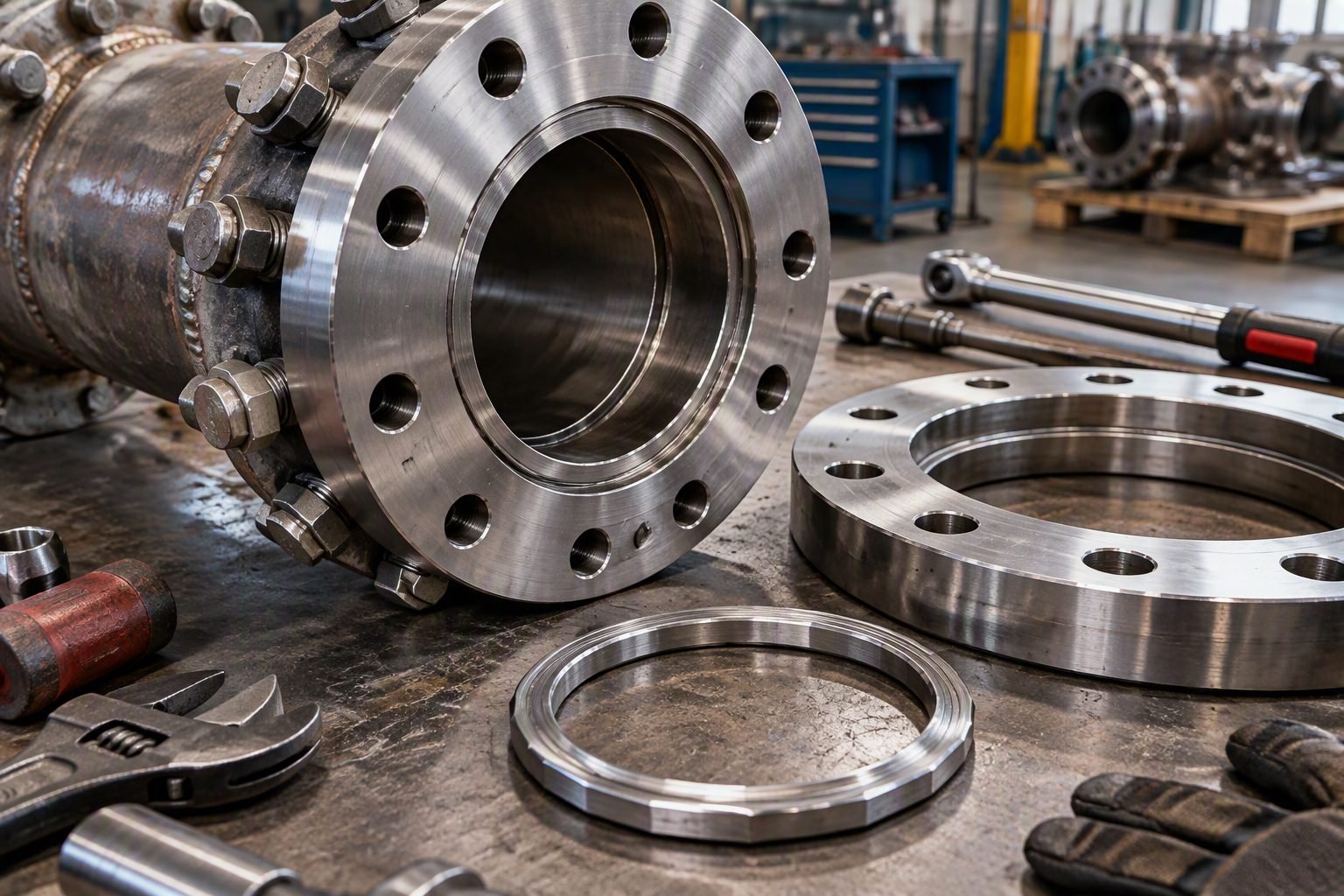
Mastering RTJ Flange Design for High-Pressure Piping Systems
In my two decades of reviewing high-pressure hydrocarbon processing units, managing joint integrity on ASME B16.5 Class 900, 1500, and 2500 piping networks remains one of the most critical mechanical engineering challenges. When dealing with severe services, standard flat or raised face soft gaskets simply cannot provide the reliable containment required. That is where ring type joint configurations become indispensable.
My operational experience working across heavy refinery retrofits proves that improper gasket hardness selection or groove machining deviations will inevitably lead to fugitive emissions during thermal transients. Mastering the precise geometric relationship between the octagonal gasket profile and the matching flange groove is mandatory for any piping designer aiming for zero-leakage performance.
Key Engineering Takeaways
- RTJ gaskets rely on controlled plastic deformation against angled groove walls rather than bulk surface compression.
- Gasket material hardness must always remain strictly lower than the mating flange material to prevent groove face gouging.
- Octagonal cross-sections outperform older oval designs in modern high-pressure environments by providing a higher contact stress concentration.
- Strict compliance with ASME dimensional tolerances ensures leak-free behavior under cyclic thermal loading.
RTJ Flange Design Mechanics and ASME B16.20 Compliance
Sealing Mechanics: Controlled metal-to-metal wedging action achieved when high bolt preloads force the octagonal ring gasket into precision-machined flange ring grooves, creating a high-integrity line contact seal per ASME B16.20.
When designing high-pressure systems operating in ASME Class 900, 1500, and 2500 tiers, understanding the fundamentals of ring type joint (RTJ) geometry is non-negotiable. Unlike raised face flanges that rely on soft gaskets distributed across a wide surface area, RTJ flanges concentrate bolt clamping force onto a narrow, high-pressure line contact zone.
The core mechanics depend entirely on the wedging action created by the 23-degree angle on the octagonal gasket side walls meeting the corresponding slanted groove walls of the flange. As bolt torque is applied, the gasket deforms slightly into the groove floor without bottoming out, generating intense localized contact stresses that far exceed internal line pressure.
Geometric Tolerances and Octagonal vs Oval Profiles
Historically, oval cross-section gaskets were utilized, but modern piping standards strongly favor octagonal profiles. The octagonal design provides a superior initial sealing line contact because its flat sealing faces mate more predictably with the conical groove walls of the flange.
Engineers must verify that the groove surface finish does not exceed 63 RMS (Root Mean Square) or 1.6 micrometers Ra. Any spiral machining tool marks or radial scratches crossing the groove floor can serve as a leak path under cyclic pressure surges.
Critical Design Warning: Hardness Mismatch
Never install a gasket material with a Brinell hardness equal to or greater than the flange material. The gasket must be the sacrificial component. If a harder gasket is installed, it will permanently deform and score the flange groove face, requiring costly in-situ machining or flange replacement.
Material Selection and Brinell Hardness Specifications
Selecting the correct metal gasket alloy is dictated by the process fluid, operating temperature, and potential corrosion mechanisms. Common metallic materials standardized under ASME B16.20 include soft iron, low carbon steel, 4% chromium-0.5% molybdenum steel, and austenitic stainless steels like Type 304 and Type 316.
For sour service applications governed by NACE MR0175 / ISO 15156, hardness restrictions are legally mandated to prevent sulfide stress cracking. For instance, soft iron gaskets must maintain a maximum hardness of 90 Brinell, while carbon steel is typically restricted to 120 Brinell maximum.
Bolt Load Calculations and Seating Stress
Designing an RTJ joint requires calculating the minimum initial bolt load required to seat the gasket and the operating load required to maintain a seal against internal pressure. The required bolt load W_m is determined using ASME Boiler and Pressure Vessel Code Section VIII, Division 1 guidelines.
The formula accounts for the contact area of the octagonal ring, the internal design pressure, and the gasket factor (m and y constants). In high-temperature hydrocarbon service, relaxation of bolt preload due to creep must also be compensated for by using high-strength alloy steel studs such as ASTM A193 Grade B7.
Proper torque tightening sequences (cross-pattern tightening across multiple passes using calibrated hydraulic tensioners) ensure uniform flange gap distribution and prevent localized crushing of the octagonal gasket ring.
Key Advantages
- Delivers exceptional seal integrity under extreme pressure classes ranging from ASME Class 900 up to Class 2500.
- Metal-to-metal line contact design is completely unaffected by high temperature extremes that would degrade soft elastomeric gaskets.
- Octagonal ring profile is completely self-centering within the matching flange groove during assembly.
- Gasket design prevents blowout failures common in flat-face gasket arrangements under sudden pressure spikes.
- Readily available in standardized dimensions compliant with ASME B16.20 and API 6A specifications.
Key Disadvantages
- Requires higher initial bolt preload force and tighter torque control compared to standard raised face soft-gasketed joints.
- Flange groove faces are susceptible to mechanical damage, scratching, and pitting corrosion during maintenance turnarounds.
- RTJ gaskets are strictly single-use components; attempting to reuse a deformed metal ring gasket will cause joint leakage.
- Machining ring grooves adds significant manufacturing complexity and cost to raw flange forgings.
- Requires greater axial pull-out clearance during piping spool installation and dismantling procedures.
High-Pressure Hydrocarbon Refining
In hydroprocessing units such as hydrotreaters and hydrocrackers operating at pressures exceeding 150 MPa and temperatures above 400 degrees Celsius, standard gaskets fail rapidly. RTJ flanges utilizing stainless steel or Inconel octagonal gaskets provide the robust containment barrier required to prevent catastrophic hydrogen leaks.
Subsea Production Wellhead Piping
Subsea oil and gas extraction manifolds experience immense external hydrostatic loads and intense internal wellbore pressures. Class 1500 and Class 2500 RTJ connections are standard across subsea tree piping and choke valve assemblies to ensure permanent leak-free isolation in inaccessible marine environments.
High-Pressure Steam Power Generation
Supercritical and ultra-supercritical thermal power plant main steam headers operate under severe thermal expansion cycles and high pressures. ASME Class 2500 RTJ flanged connections on high-pressure feedwater and steam injection lines prevent joint relaxation and steam cutting failures.
Sour Gas Processing and Transmission
Pipelines carrying high concentrations of hydrogen sulfide and carbon dioxide require specialized metallurgy. RTJ flanges manufactured from NACE-compliant low-alloy steels paired with soft iron or 316L stainless steel gaskets ensure long-term structural integrity in corrosive acid gas service.
RTJ Flange Dimensional and Pressure Ratings
Ring-Type Joint (RTJ) flange designs rely on precise dimensional interchangeability between the metallic gasket and the flange groove recess. In high-pressure piping systems operating at ASME Class 900 and above, standard raised face gaskets are structurally inadequate due to excessive bolt load relaxation and creep. To maintain seal integrity under severe cyclic loading and elevated temperatures governed by ASME B16.5 and ASME B16.20, engineering teams must evaluate specific ring number designations against pipeline design pressures and temperature derating factors.
The following engineering reference table outlines critical dimensional parameters, including ring number compatibility, approximate pitch diameters, and groove dimensions for high-pressure service. These values ensure proper metal-to-metal wedging action, which forms the primary pressure seal inside the gasket groove.
| ASME Ring Number | Nominal Pipe Size (NPS) | Class 900 Pitch Diameter (mm) | Octagonal Width (mm) | Groove Depth (mm) |
|---|---|---|---|---|
| R11 | 1/2 in | 38.10 | 7.92 | 6.35 |
| R16 | 1 in | 55.56 | 9.53 | 7.92 |
| R24 | 2 in | 82.55 | 11.13 | 9.53 |
| R31 | 3 in | 120.65 | 11.13 | 9.53 |
| R37 | 4 in | 149.22 | 11.13 | 9.53 |
| R45 | 6 in | 211.12 | 14.27 | 11.13 |
| R49 | 8 in | 269.88 | 14.27 | 11.13 |
Designers must verify that flange groove surface finishes do not exceed 1.6 micrometers (63 microinches) Ra to ensure the octagonal gasket flows properly into micro-asperities under bolt tension.
Technical Mapping & Specifications Matrix
To successfully execute high-pressure piping design, engineers must understand the complex network of metallurgical requirements, dimensional tolerances, and pressure containment standards governing Ring-Type Joint assemblies. The interaction between soft metallic gaskets and hardened flange groove walls requires precise material selection to prevent galvanic corrosion, thread galling, and premature plastic deformation failure.
The matrix below maps essential engineering entities, governing codes, structural acronyms, and operational boundaries. This reference assists multidisciplinary piping teams in harmonizing material test reports (MTRs) with strict project specifications.
| Entity / Parameter | Governing Standard | Technical Specification | Operational Purpose |
|---|---|---|---|
| Octagonal RTJ Gasket | ASME B16.20 | Soft iron or 316L SS (Hardness < 90 HB) | Forms wedge seal inside flange groove under bolt load. |
| High-Pressure Flange | ASME B16.5 / ASME B16.47 | Class 900, 1500, and 2500 forged steel | Provides structural containment for severe service fluids. |
| Flange Groove Finish | ASME B16.5 | 1.6 to 3.2 micrometers Ra (machined finish) | Ensures controlled plastic flow of gasket into groove walls. |
| Stud Bolt Tensioning | ASME PCC-1 | Controlled torque or hydraulic tensioning | Achieves uniform gasket compression without flange tilting. |
| Hardness Differential | ASTM E10 / NACE MR0175 | Gasket Brinell hardness < Flange groove hardness | Guarantees gasket deformation without gouging flange sealing faces. |
Cross-referencing these entities during the procurement stage prevents catastrophic material mismatches, particularly in sour gas and high-pressure hydrocarbon processing units.
RTJ Flange Site Verification Checklist
Verifying high-pressure piping assemblies prior to hydrostatic testing requires strict adherence to quality control protocols. In my field engineering experience, overlooking minor groove surface imperfections or using incorrect bolt lubrication leads directly to joint failure during initial pressurization. Field technicians must systematically inspect every component, ensuring that hardware dimensions, material grades, and cleanliness align perfectly with engineering data sheets and construction drawings.
The structured verification workflow below outlines essential site inspection gates. Complete each checkpoint sequentially and sign off on the inspection traveler before releasing the piping circuit for bolt torquing and pressure testing.
Field Quality Inspection Checkpoints
- Groove Inspection: Verify flange groove sealing surfaces are entirely free of radial tool marks, scratches, pitting, or rust accumulation using a 10x magnifying glass and surface comparator plates.
- Gasket Verification: Confirm octagonal gasket material grade matches line class specifications (ASME B16.20) and check that gasket surface hardness is lower than the flange forging to prevent groove scoring.
- Reusable Gasket Prohibition: Inspect incoming gaskets to ensure zero reusability of previously compressed RTJ rings. Never reinstall a deformed or previously torqued metal ring gasket.
- Alignment & Gap Check: Check parallel flange face alignment and ensure parallel standoff gap is uniform around the circumference before inserting stud bolts without leveraging or forcing.
- Lubrication Application: Apply approved anti-seize lubricant strictly to stud bolt threads and nut bearing faces per ASME PCC-1 guidelines, avoiding contamination of the gasket groove.
- Multi-Pass Torquing Sequence: Execute controlled 4-step cross-pattern bolt tightening sequence (30%, 60%, 100%, and 100% rotational pass) using calibrated hydraulic tensioners or torque wrenches.
Document all final bolt elongation or torque readings on the quality control turnover package to maintain full traceability for high-pressure piping documentation.
Field Case Study: Real-World Application
During commissioning of a Class 900 high-pressure natural gas booster station, our engineering team investigated recurring fugitive emissions and joint weeping on several 8-inch suction manifold connections operating at 15.2 MPa. Initial site reviews indicated that despite following standard torque tables, certain Ring-Type Joint flanges failed acoustic emission testing during pressurization cycles.
The Problem Analysis
Investigation revealed multiple underlying mechanical violations during assembly:
- Maintenance crews reused soft iron octagonal ring gaskets from a previous hydrostatic test hydro-test loop.
- Flange groove faces contained residual machining chatter marks exceeding 3.2 micrometers Ra.
- Bolt tightening was performed using a single-pass pneumatic impact wrench without a cross-pattern sequence.
- Hardness testing showed the replacement gaskets possessed higher Brinell hardness than the forged steel flange grooves.
The Engineering Outcome
Implementing corrective engineering actions restored full leak-tight integrity:
- Replaced all improper gaskets with new ASME B16.20 compliant 316L stainless steel octagonal ring gaskets.
- Re-machined damaged flange grooves in-situ to achieve the required 1.6 micrometers surface finish.
- Enforced controlled hydraulic bolt tensioning following ASME PCC-1 Appendix F clamping load calculations.
- Successfully completed hydrostatic testing at 1.5 times design pressure with zero leakage or acoustic anomalies.
This case underscores the absolute necessity of adhering strictly to metallic gasket selection rules and controlled bolting procedures in high-pressure piping systems.
Frequently Asked Engineering Questions
Can octagonal RTJ gaskets be reused during plant turnaround maintenance?
In my professional experience, reusing octagonal ASME B16.20 ring-type joint gaskets is strictly prohibited across high-pressure hydrocarbon service lines.
- Plastic deformation: The gasket octagonal profile work-hardens upon initial bolt-up to lock into the flange groove surface imperfections.
- Sealing integrity risk: A previously compressed gasket will never match the exact seating geometry of a newly machined flange groove.
- Standard compliance: ASME PCC-1 guidelines mandate replacing metallic gaskets during every joint disassembly to prevent catastrophic leaks.
What is the primary difference between oval and octagonal RTJ gasket profiles?
The contact geometry and groove compatibility separate these two standard profiles governed by ASME B16.20.
- Contact stress: Octagonal profiles provide a higher initial contact stress due to line-contact sealing against the 23-degree flange groove walls.
- Interchangeability: Octagonal gaskets can fit both modern flat-bottom and old round-bottom grooves, whereas oval gaskets only fit round-bottom grooves.
- Application standard: Modern Class 900 and above installations exclusively specify octagonal gaskets for superior high-pressure performance.
How do you prevent galling between stainless steel RTJ flanges and gaskets?
Austenitic stainless steel components are highly susceptible to galling during high-torque bolt-up procedures.
- Hardness differential: Ensure the gasket material is slightly softer than the flange groove to encourage controlled deformation without tearing.
- Lubrication protocols: Apply approved high-temperature anti-seize paste strictly to stud bolt threads, avoiding contamination of the sealing faces.
- Controlled tightening: Utilize calibrated hydraulic tensioners to maintain even parallel gap closure across the flange face.
Why are RTJ flanges mandated for Class 900 and higher piping systems?
Standard raised face gaskets cannot reliably contain extreme internal pressures without blowing out under cyclic loads.
- Metal-to-metal wedging: RTJ ring groove designs utilize internal fluid pressure to energize the seal against the flange walls.
- Blowout resistance: The enclosed metallic ring prevents joint separation and catastrophic media release under severe pressure spikes.
- Design standards: ASME B16.5 and ASME B16.47 dictate RTJ usage for high-energy refinery and power plant applications.
What surface finish roughness is required for RTJ flange groove faces?
Maintaining precise machining tolerances on the groove flank surfaces is critical for establishing metal contact sealing.
- Roughness limit: ASME B16.5 specifies that the side wall groove finish must not exceed 63 micro-inches (1.6 micrometers) Ra.
- Inspection methods: Use surface comparator plates and profilometers during shop fabrication to verify tool mark depth.
- Flaw rejection: Any radial tool marks or scratches crossing the 23-degree sealing flanks will cause fugitive emissions and require weld repair.
Field Recommendation
-
If assembling high-pressure Class 900 stainless steel systems, choose silver-plated soft iron octagonal RTJ gaskets to prevent galling during initial bolt torque application while maintaining compliance with ASME B16.20 material hardness differentials.
-
When inspecting legacy plant piping with round-bottom grooves, specify oval RTJ gaskets rather than octagonal rings to ensure proper initial line contact and avoid localized stress concentrations on worn groove roots.
-
During major turnaround maintenance scopes, reject any proposal to reuse existing metallic ring joint gaskets; enforce a strict site rule requiring brand-new ASME B16.20 certified gaskets for every single flange joint break.
-
If surface profilometer readings on flange groove flanks exceed 63 micro-inches Ra, mandate immediate on-site machining or weld buildup rather than attempting to compensate with thicker gasket seating loads, which violates ASME PCC-1 integrity standards.
Complete Course on
Piping Engineering
Check Now
Key Features
- 125+ Hours Content
- 500+ Recorded Lectures
- 20+ Years Exp.
- Lifetime Access
Coverage
- Codes & Standards
- Layouts & Design
- Material Eng.
- Stress Analysis
