Rock Anchored Wind Turbine Foundation Design and Bedrock Uplift Checks
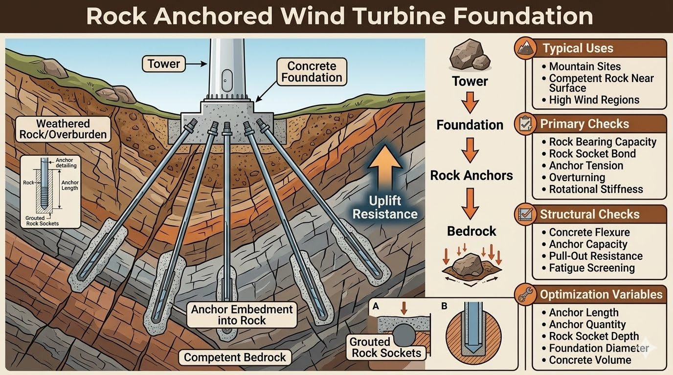
In my two decades of heavy industrial and energy infrastructure engineering, designing support systems for multi-megawatt wind turbines on challenging mountainous terrain has always demanded rigorous geotechnical integration. When overburden is shallow and competent bedrock sits close to the surface, massive gravity-based spread footings become uneconomical and prone to differential settlement. Instead, we rely on a rock anchored wind turbine foundation, which uses high-strength steel tendons anchored deep into sound rock mass to provide exceptional uplift and rotational stiffness.
The load path in this foundation type is direct yet complex: aerodynamic thrust from the rotor is transferred through the turbine tower, distributed across the concrete pedestal and ring footing, and finally resolved into tension and shear forces absorbed by the rock anchors and bedrock socket. Understanding this mechanics continuum is essential for avoiding catastrophic geotechnical failures under cyclic fatigue loading.
Key Engineering Takeaways
- Load path transitions from tower moments into multi-tendon rock anchor tension arrays.
- Requires comprehensive verification of rock socket bond strength and concrete bearing limits.
- Cyclic fatigue screening is mandatory per ASCE guidelines to prevent tendon degradation.
- Optimization focuses on balancing anchor length, socket embedment depth, and concrete volume.
Rock Anchored Wind Turbine Foundation Analysis and Design
Load Path and Force Distribution Mechanics
Wind turbines impose severe dynamic overturning moments (M), horizontal shear forces (V), and vertical dead loads (P) onto the foundation. In a rock-anchored system, the overturning moment does not rely solely on the self-weight of a massive concrete ballast block. Instead, the moment is resisted by a couple formed by compressive bearing stress on the leeward rock interface and intense tensile forces developed in the windward rock anchors.
When designing this load path, geotechnical engineers must evaluate the stiffness ratio between the concrete footing and the underlying rock mass. Because rock is significantly stiffer than mass concrete, load transfer is highly concentrated at anchor locations. This necessitates rigorous finite element modeling (FEM) to map localized stress concentrations around the rock socket collar and grout-rock interface.
Geotechnical Failure Modes and Limit States
Evaluating a rock-anchored foundation involves checking multiple independent failure mechanisms governed by ASCE and PTI (Post-Tensioning Institute) standards. We must screen against both structural material failures and geotechnical mass-failure modes:
- Global Rock Mass Uplift: The entire cone or wedge of bedrock surrounding the anchor group could pull out under extreme hurricane wind gusts.
- Rock-Grout Bond Failure: Shear failure along the cylindrical interface between the steel-encased grout body and the borehole wall.
- Steel Tendon Yielding: Overstressing of high-tensile prestressing steel strands due to dynamic load magnification.
- Concrete Punching Shear: Localized cone shear failure of the concrete pedestal directly beneath the anchor chair assembly.
Critical Design Warning: Jointed Bedrock Masses
Never assume homogeneous intact rock properties when designing grouted sockets. Presence of orthogonal joint sets, slickensides, or weathered clay seams drastically reduces bond strength. In-situ pressure meter testing and core logging are mandatory to establish lower-bound rock mass ratings (RMR) before finalizing socket embedment lengths.
Mathematical Formulation for Rock Socket Bond Capacity
The ultimate pull-out resistance (P_u) of a grouted rock anchor is primarily a function of the grout-to-rock bond strength, socket diameter, and embedment length. The nominal bond capacity is calculated using the cylindrical shear model:
P_u = pi * D_s * L_s * tau_all
Where D_s is the diameter of the rock socket, L_s is the bonded embedment length into competent rock, and tau_all is the allowable bond stress between the neat cement grout and the rock borehole wall. Allowable bond stress is empirically derived from unconfined compressive strength (q_u) of the rock core, typically limited to 10\% to 15\% of q_u for smooth boreholes, adjusted for joint conditions.
Dynamic Fatigue Screening and Prestress Losses
Wind turbines experience millions of load reversals over their 25-year operational lifespan. This introduces severe fatigue risks to high-strength rock anchors. Fatigue screening per ASCE guidelines requires verifying that stress range fluctuations in the steel tendons remain well below the endurance limit under operational spectrum loading.
Furthermore, long-term prestress losses must be accounted for in the initial tensioning protocol. These losses stem from steel relaxation, concrete creep and shrinkage, and anchor head seating slip. Post-tensioning force is typically locked off at 70\% to 80\% of guaranteed ultimate tensile strength (GUTS), with provisions for lift-off testing during commissioning.
Key Advantages
- Drastically reduced concrete volume compared to massive gravity base footings.
- Exceptional overturning resistance via direct high-tensile bedrock coupling.
- Minimal excavation footprint required in mountainous or rocky terrain sites.
- Superior rotational stiffness reducing tower-base dynamic deflection amplitude.
- Highly effective on sloping or undulating sites with shallow competent bedrock.
Key Disadvantages
- Demands extensive geotechnical core drilling and in-situ pull testing.
- Complex installation requiring specialized heavy drilling and grouting rigs.
- Long-term corrosion protection of steel tendons is critical and maintenance-intensive.
- High sensitivity to geological anomalies, fault lines, and variable rock quality.
- Skilled post-tensioning specialist contractors required on-site during construction.
Mountain Ridge Wind Farms
Mountainous installations frequently feature exposed or thinly weathered bedrock ridgelines with extreme wind shear profiles. Constructing conventional massive gravity slabs is structurally impractical due to steep slopes and restricted transport access for thousands of cubic meters of ready-mix concrete. A rock anchored foundation utilizes the stable ridge rock mass, anchoring the turbine safely with a fraction of the concrete footprint.
High-Capacity Offshore-to-Coastal Transition Sites
Coastal cliff tops and near-shore rocky headlands subjected to severe marine gale forces experience intense overturning moments. These locations benefit immensely from grouted rock sockets that transfer cyclical uplift loads directly into deep, unweathered granite or limestone formations, preventing sliding and rock-toe crushing.
High-Wind Inland Plateau Developments
Inland high-wind resource areas with thin glacial till or alluvial overburden resting on competent sedimentary bedrock require deep foundation solutions. Rock anchors penetrate through the incompetent overburden layer and bond directly into the underlying competent stratum, bypassing weak upper soils and mitigating differential settlement risks.
Repowering Existing Wind Turbine Sites
When upgrading older, smaller wind turbines to modern multi-megawatt units on the same plot, existing foundations are often undersized for the new overturning loads. Rather than demolishing massive concrete blocks, engineers frequently retrofit post-tensioned rock anchors around the existing foundation perimeter to increase uplift capacity and accommodate larger turbine ratings.
Rock Anchor Design Parameters and Engineering Limits
Engineering a robust foundation system requires meticulous evaluation of geometric constraints, material properties, and load transfer capacities. The following engineering data table outlines the core parameters, allowable limits, and governing standards associated with high-capacity rock anchors used in modern wind turbine installations.
Design professionals must cross-reference these empirical limits with site-specific geotechnical investigations. Adherence to these criteria ensures structural integrity against cyclic wind loads and overturning moments.
| Parameter Description | Typical Design Value / Range | Governing Standard | Engineering Notes |
|---|---|---|---|
| Rock Socket Diameter | 75 mm to 150 mm | PTI DC35.1 | Must accommodate tendon centralization and uniform grout annulus thickness. |
| Grout-Rock Bond Stress | 0.7 MPa to 2.1 MPa | ASTM A722 | Directly governed by Unconfined Compressive Strength of the intact rock core. |
| Anchor Embedment Length | 3.0 m to 12.0 m | ASCE | Calculated to prevent pull-out failure of the rock cone mass. |
| Preload Force Percentage | 60% to 70% of GUTS | PTI DC35.1 | Minimizes cyclic fatigue stress range under operational thrust loads. |
| Concrete Compressive Strength | 40 MPa to 55 MPa | ACI 318 | High early and long-term strength required for dynamic load transfer. |
Note: All values must be verified via site-specific pull-out testing prior to final mass concrete placement.
Technical Mapping & Specifications Matrix
Complex geotechnical and structural interfaces demand strict organization of design entities, material specifications, and regulatory codes. The matrix below structures the critical variables governing rock anchor integration, fatigue resistance, and load path continuity.
System architects utilize this mapping matrix to align finite element boundary conditions with field testing protocols, ensuring comprehensive compliance across all structural domains.
| Entity Category | Structural Acronym | Physical Parameter | Standard Reference |
|---|---|---|---|
| Ultimate Tensile Strength | GUTS | Steel Tendon Capacity | ASTM A722 |
| Rock Mass Rating | RMR | Bedrock Quality Index | Bieniawski System |
| Geological Strength Index | GSI | Jointed Rock Mass Characterization | Hoek-Brown Criterion |
| Post-Tensioning Institute | PTI | Anchor Hardware Guidelines | PTI DC35.1 |
| American Concrete Institute | ACI | Reinforced Concrete Design | ACI 318 |
Entity mapping guarantees full traceability from initial core drilling logs to final tensioning records on site.
Site Verification Checklist for Rock Anchored Foundations
Rigorous site quality control is essential before, during, and after rock anchor installation for wind turbine foundations. Following a structured verification workflow ensures that all geotechnical assumptions match actual subsurface conditions encountered during excavation and drilling.
The checklist below details critical inspection gates required to satisfy quality assurance programs mandated by ASCE and PTI specifications.
Phase 1: Pre-Drilling and Subsurface Validation
- Verify geotechnical boring logs confirm competent bedrock depth matching design assumptions.
- Check groundwater table level and assess potential inflow rates into open anchor sockets.
- Inspect drilling rig calibration, alignment guides, and plumbness verification tools.
Phase 2: Socket Drilling and Grouting Execution
- Confirm rock socket diameter and depth meet or exceed structural engineering drawings.
- Execute high-pressure water flushing to remove all drill cuttings and loose debris from sockets.
- Test neat cement grout fluidity, bleeding rate, and compressive strength via cylinder samples.
- Verify tremie pipe placement ensures bottom-up grouting without air pockets or voids.
Phase 3: Tendon Installation and Tensioning
- Inspect corrosion protection sheathings, centralizers, and encapsulation integrity on all anchor tendons.
- Calibrate hydraulic jack pressure gauges and load cells prior to proof and lock-off testing.
- Perform proof testing on selected anchors to 80% of GUTS per PTI DC35.1 standards.
All signed inspection checklists must be archived in the project quality management database alongside certified concrete batch tickets.
Field Case Study: Real-World Application
An installation of a 4.5 MW wind turbine on a complex mountainous ridge revealed unexpected geological anomalies that tested conventional rock anchor design limits. Subsurface conditions varied abruptly from weathered gneiss to highly fractured schist, threatening foundation uplift resistance.
The engineering team executed a comprehensive redesign to safeguard the structural load path from the tower base through the mass concrete foundation into competent bedrock strata.
Case Problem: Encountering Fractured Rock and High Groundwater Pressures
Unforeseen bedrock fracturing and artesian groundwater flows compromised initial rock socket friction values and threatened grout integrity during curing.
- Drilled rock sockets experienced localized collapse in highly weathered schist zones prior to casing installation.
- Artesian water pressure diluted neat cement grout mixtures, reducing 28-day compressive strengths below structural requirements.
- Preliminary pull-out testing indicated bond stress transfer failures at lower anchor embedment depths.
- Cyclic wind gust reversals threatened premature fatigue degradation of unbonded tendon lengths.
Faced with these severe geotechnical hurdles, the structural and geotechnical engineering task force deployed an aggressive remediation strategy compliant with ASCE standards.
Case Outcome: Successful Remediation via Pressure Grouting and Extended Sockets
Implementing targeted pressure grouting and deeper socket embedment successfully restored full uplift capacity and achieved long-term structural stability.
- Introduced temporary steel casing sleeves through weathered overburden to stabilize open socket excavation walls.
- Switched to micro-silica modified expansive grout formulations resistant to groundwater dilution and washout.
- Increased rock socket embedment depth by 35 percent to mobilize deeper, competent gneiss strata friction.
- Completed successful proof testing on 100 percent of production anchors with zero creep movement recorded over 24-hour holds.
Recommendation for future mountain wind sites: Always perform exploratory core drilling at every turbine pad location rather than relying solely on array-wide geophysical seismic profiling.
Frequently Asked Engineering Questions
What governs rock socket bond strength in tension anchors?
Rock socket bond capacity depends heavily on the interfacial shear transfer between the grout and the surrounding competent bedrock mass.
- Unconfined compressive strength of both grout and rock mass
- Socket wall roughness profile and mechanical keying effects
- Proper pressure grouting techniques to eliminate micro-annuli
- Minimum embedment length calculated per ACI geotechnical guidelines
How is cyclic fatigue managed in rock-anchored turbine bases?
Wind turbine operations subject anchor rods and rock interfaces to millions of high-amplitude reversing tension cycles over their design life.
- Pre-tensioning anchor tendons to reduce stress range fluctuations
- Selecting high-yield corrosion-protected alloy steel rods
- Limiting maximum stress amplitudes per ASCE fatigue design criteria
- Detailed finite element analysis modeling dynamic load transfer
What are the main causes of rock anchor corrosion on site?
Subsurface moisture migration and aggressive groundwater chemistries pose severe degradation risks to unstressed steel tendons.
- Aggressive chemical species like chlorides and sulfates in groundwater
- Inadequate neat cement or epoxy grout coverage thickness
- Breached corrosion protection sheathing during drilling and installation
- Stray electrical currents from nearby grounding or substation grids
When should a deep rock socket be preferred over shallow spread footings?
Site geomorphology, extreme overturning moments, and shallow competent bedrock dictate the structural transition point.
- High overturning moments driven by multi-megawatt turbine hub heights
- Competent rock outcrops located near the natural surface grade
- Steep mountain terrain where massive gravity foundations are impractical
- Sites requiring minimal footprint and reduced mass excavation volumes
What mandatory proof testing is required for production rock anchors?
Rigorous physical load testing validates installation quality and confirms design safety factors before turbine erection begins.
- Proof testing of a designated percentage of production anchors
- Creep monitoring under sustained high-percentage proof loads
- Elastic rebound measurement to isolate free tendon length
- Immediate rejection protocols for anchors exhibiting excessive creep
Field Recommendation
Based on decades of wind farm site execution and rigorous geotechnical design reviews, I advise engineering teams to implement the following critical measures during structural deployment:
- If exploratory core drilling reveals highly fractured or weathered rock layers near the upper bedrock interface, mandate an extended primary rock socket depth rather than relying on shallow friction zones to prevent progressive bond failure.
- Specify double corrosion protection (DCP) encapsulated anchor tendons on all mountain and high-humidity sites where acidic groundwater or aggressive chemical species could initiate premature stress corrosion cracking.
- Enforce strict on-site pull-out proof testing for at least ten percent of total production anchors, monitoring creep behavior closely under sustained peak loads before permitting any turbine tower erection activities.
- Coordinate structural foundation ring geometry with geotechnical boring logs early in the design phase to optimize concrete volume while maintaining adequate rotational stiffness and overturning resistance under extreme wind gusts.
Complete Course on
Piping Engineering
Check Now
Key Features
- 125+ Hours Content
- 500+ Recorded Lectures
- 20+ Years Exp.
- Lifetime Access
Coverage
- Codes & Standards
- Layouts & Design
- Material Eng.
- Stress Analysis
