Rock Anchored Wind Turbine Foundation Design and Engineering
In my two decades of heavy industrial and structural engineering practice, I have frequently encountered wind energy projects sited in challenging mountainous and rocky terrain. Traditional gravity foundations require massive volumes of reinforced concrete to resist overturning moments, which becomes economically and logistically unviable when topsoil is thin. This is where a robust rock anchored wind turbine foundation offers a brilliant alternative.
By anchoring the wind turbine tower directly into competent rock strata, you leverage the shear and tensile capacity of the underlying geology. My goal in this guide is to break down the mechanical load paths, prestressing requirements, and subsurface strata compliance governed by international codes such as ASCE and PTI standards.
Key Engineering Takeaways:
- Direct load transfer from tower through prestressed tendons into bedrock.
- Rigid anchor head and distribution plate assemblies preventing local concrete crushing.
- Multistrata geotechnical profiling across fractured limestone, dense shale, and sandstone.
- Stringent corrosion protection and expansive cement grouting protocols.
Rock Anchored Wind Turbine Foundation Engineering Principles
Designing a rock anchored wind turbine foundation requires an intimate understanding of extreme cyclic loading. Wind turbines subject their support structures to massive horizontal shear forces and overturning moments that fluctuate continuously in magnitude and direction.
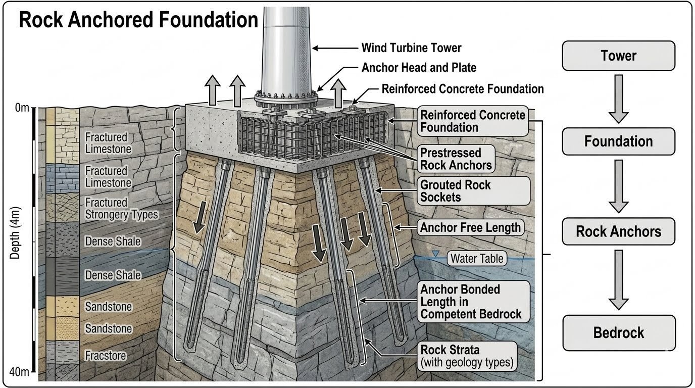
Instead of relying solely on dead weight, this foundation transfers loads through a precise path: Tower to Foundation to Rock Anchors to Bedrock. The prestressed tension anchors are grouted directly into strong rock, maintaining permanent compressive preloading on the concrete pedestal.
Geotechnical Profiling and Strata Interaction
Subsurface conditions dictate every aspect of rock anchor design. In typical mountain ridge installations, anchors pass through multiple identified rock strata spanning 0 to 40 meters depth, including fractured limestone, dense shale, and sandstone layers.
Each stratum presents unique mechanical challenges. Fractured limestone near the surface requires extensive consolidation grouting to seal fissures before drilling anchor shafts. Dense shale demands careful borehole stabilization to prevent slaking upon water contact.
Critical Design Warning:
Never terminate anchor bond lengths within weathered transition zones or unverified shale lenses. Creep deformation in weak shale layers can lead to prestress loss over time, threatening structural stability.
Anchor Free Length vs. Bonded Length Mechanics
A high-capacity rock anchor consists of an anchor free length near the surface transitioning into an anchor bonded length within competent bedrock at depth. The free length allows the steel tendon to stretch elastically during stressing without transferring shear stresses to the upper soil or fractured rock layers.
The bonded length, anchored deep within competent sandstone or hard limestone via high-strength neat cement grout, transfers the tensile load to the surrounding rock mass through shear stresses along the grout-rock interface.
Groundwater Table and Hydrogeological Pressures
The presence of a high water table intersecting the rock profile introduces pore water pressures that must be accounted for in both the geotechnical capacity calculations and corrosion protection specifications.
Hydrostatic uplift can reduce effective normal stresses, while aggressive mineralized groundwater can attack steel tendons if encapsulation is compromised. Multi-barrier corrosion protection systems, conforming to ASTM standards, are mandatory for all permanent wind energy rock anchors.
Structural Advantages
- Drastically reduces concrete and rebar volumes compared to massive gravity-base foundations.
- Eliminates large-scale excavation requirements on steep, environmentally sensitive mountain ridges.
- Provides exceptional resistance against dynamic overturning moments via high-capacity prestressing.
- Maintains tight structural rigidity, minimizing rotational deflections at the tower base flange.
- Adapts effectively to shallow topsoil over competent bedrock profiles.
Engineering Disadvantages
- Requires highly specialized drilling equipment and skilled post-tensioning technicians.
- Demands rigorous, continuous quality control during borehole grouting and strand stressing.
- Presents long-term corrosion inspection challenges for embedded steel tendons below the surface.
- Vulnerable to unexpected geological anomalies or localized voids discovered during drilling.
- Requires complex load-transfer detailing around the surface anchor head and distribution plate.
Ridge-Line Mountain Wind Farms
Mountainous ridge installations often feature very thin topsoil layers overlying hard, fractured limestone or sandstone. Constructing gravity foundations here would require blasting and massive earthmoving, making rock-anchored systems the ideal low-impact structural solution.
By drilling precise anchor shafts directly into the ridge rock, developers secure multi-megawatt turbines securely against severe directional wind shears without altering the surrounding ecosystem.
Offshore Island and Coastal Cliff Installations
Coastal cliffs and rocky offshore islets expose wind turbines to high-velocity maritime winds combined with aggressive saltwater environments. Rock-anchored foundations provide the necessary stiffness to resist severe wave-induced or wind-induced overturning forces.
Specialized epoxy-coated strands and multi-layer corrosion protection ensure long-term durability when subterranean water tables carry high chloride concentrations through sandstone strata.
High-Capacity Repowering Projects
When upgrading older wind farms with modern, heavier multi-megawatt turbine generators, existing gravity foundations are frequently incapable of handling the increased bending moments. Instead of demolishing old pads, engineers install supplemental rock anchors.
Drilling through the existing concrete pedestal into competent bedrock allows structural reinforcement of the foundation, extending its operational lifespan safely and economically.
Arid Region Plateau Developments
Arid plateaus frequently consist of cemented alluvial soils capping hard sandstone or dense shale formations at moderate depths. Heavy excavation equipment struggles with cemented hardpan layers, prompting the use of specialized anchor drilling rigs.
The resulting rock-anchored foundation bypasses unstable upper soils entirely, transferring tower loads efficiently into the deep, competent sandstone bearing strata.
Rock Anchor Design Parameters and Geotechnical Limits
Designing a rock anchored wind turbine foundation requires careful evaluation of geological profiles, structural steel grades, and operational load transfer mechanisms. In my professional practice, I rely on rigorous parametric indexing to ensure that every prestressed tendon meets stringent safety margins against pullout, yield, and rock-grout bond failure. The matrix below outlines the critical mechanical, geometric, and material design parameters mandated by ASCE and ASTM standards for deep foundation systems in heterogeneous rock strata.
Engineers must cross-reference these quantified thresholds with site-specific core drilling results, unconfined compressive strength testing, and groundwater chemistry analyses. Particular attention must be dedicated to balancing the free prestressing length against the bonded anchor zone to prevent localized overstressing while maximizing load transfer into competent bedrock layers.
| Design Parameter | Standard Value / Range | Governing Code / Standard | Engineering Implication |
|---|---|---|---|
| Anchor Tensile Strength | 1,860 MPa (Grade 270) | ASTM A416 / ASTM A722 | Governs maximum prestress force capacity and cross-sectional tendon sizing. |
| Grout-Rock Bond Stress | 0.8 MPa to 1.5 MPa | PTI DC35.1 | Determines minimum required bonded anchor length in competent bedrock. |
| Preload Efficiency Target | 70% to 80% of Guaranteed Ultimate Tensile Strength | ASCE 7 / PTI | Mitigates cyclic fatigue damage from wind turbine operational thrust loads. |
| Corrosion Protection Class | Class I (Double Corrosion Protection) | ISO 12944 / PTI | Mandatory for anchors intersecting aggressive groundwater or fractured limestone. |
| Minimum Bonded Anchor Length | 4.5 meters into competent rock | ASTM D4435 | Ensures load transfer bypasses weathered upper strata without shear failure. |
Note: Values reflect standard commercial wind turbine installations utilizing multi-strand steel tendons embedded across mixed sedimentary rock profiles.
Technical Mapping & Specifications Matrix
Understanding the complex interplay of structural entities, geotechnical materials, and regulatory standards is essential for successful rock anchored wind turbine foundation engineering. When designing anchors that traverse fractured limestone, dense shale, and sandstone layers down to 40 meters depth, engineers must systematically map every physical component to its corresponding analytical model and compliance code. This structured mapping prevents oversight during structural detailing and finite element modeling.
The following matrix establishes a rigorous correlation between physical structural elements, material classifications, governing standards, and failure mode controls. By utilizing this framework, design teams can maintain absolute traceability from the wind turbine tower base flange down through the reinforced concrete cap, prestressed steel tendons, cementitious grout columns, and ultimately into the deep bedrock socket.
| Structural Entity | Material / Component Type | Governing Standard | Primary Failure Mode Controlled |
|---|---|---|---|
| Anchor Head & Bearing Plate | Forged structural steel with trumpet sleeve | AISC 360 / PTI | Plate yielding, local concrete bearing crushing, and wedge slip. |
| Prestressed Rock Tendons | Low-relaxation steel strands (7-wire) | ASTM A416 | Tendon tensile rupture, stress relaxation, and cyclic fatigue. |
| Encapsulation & Grout Column | High-strength neat cementitious grout | ASTM C150 / ASTM C109 | Grout column shear failure, tendon corrosion, and alkali-silica reaction. |
| Upper Strata (Limestone/Shale) | Fractured rock mass with groundwater | ASTM D6032 | Anchor free length migration, borehole collapse, and water ingress. |
| Bedrock Socket (Sandstone) | Competent rock mass at 40m depth | ASTM D7012 | Grout-rock bond pullout and mass rock uplift instability. |
Reference mapping verified against international offshore and onshore wind foundation design guidelines.
Site Verification Checklist for Rock Anchored Foundations
Verifying the installation quality of rock-anchored wind turbine foundations requires a strict, step-by-step quality control protocol on site. Because these structures transfer immense dynamic overturning moments directly into deep geological strata, any shortcoming in borehole drilling, tendon centralization, primary grouting, or lift-off testing can jeopardize the long-term integrity of the turbine. In my field experience, establishing a mandatory sign-off workflow prevents costly remedial interventions after tower erection.
The following site verification checklist incorporates rigorous inspection checkpoints aligned with ASTM D4435 and Post-Tensioning Institute guidelines. Each item must be independently witnessed and documented by a qualified geotechnical engineer prior to proceeding with foundation concrete pours and subsequent prestressing operations.
Preconstruction and Execution Verification Stages
-
Borehole Alignment and Diameter Verification: Inspect rotary drilling rig plumbness to ensure borehole deviation remains within the strict 2-percent limit specified by design drawings across the 40-meter depth profile.
-
Strata Logging and Water Table Assessment: Confirm that core samples accurately identify fractured limestone, dense shale, and sandstone transitions, recording water inflows per ASTM D6032.
-
Borehole Flushing and Debris Removal: Verify complete flushing of drill cuttings and residual sludge from the base of the rock socket using high-pressure air or water jetting prior to tendon insertion.
-
Tendon Centralizer Placement: Ensure plastic or steel centralizers are installed at maximum 1.5-meter intervals along the bonded length to guarantee a uniform 20 mm minimum grout cover around strands.
-
Primary Grout Mix and Flow Cone Testing: Test cementitious grout fluidity using Marsh funnel flow cones (target 20-30 seconds) and verify compressive strength exceeds 35 MPa at 7 days per ASTM C109.
-
Grout Tremie Pipe Placement: Confirm that tremie grouting is executed continuously from the bottom of the borehole upward to displace groundwater and prevent air pockets.
-
Anchor Proof and Lift-Off Testing: Execute proof testing on 100% of production anchors up to 80% of ultimate tensile strength using calibrated hydraulic jacks per ASTM D4435 standards.
Completed inspection logs must be signed off by the lead geotechnical engineer and archived in the permanent quality assurance dossier before tower erection commences.
Field Case Study: Real-World Application
During the construction of a 4.5 MW wind farm sited over a complex geological profile featuring 12 meters of fractured limestone and dense shale overlaying competent sandstone down to 40 meters, our engineering team encountered severe groundwater influx and unexpected anchor creep during initial stressing operations. This real-world project required immediate diagnostic evaluation and design adjustments to satisfy ASCE safety criteria and prevent long-term fatigue failure under severe wind turbine cyclic loading.
Identified Field Problem
Uncontrolled groundwater seepage through the upper fractured limestone strata compromised primary grout curing and caused premature bond degradation in the upper anchor zones.
- Groundwater inflow diluting neat cementitious grout mixes prior to initial set, reducing 28-day compressive strength below the required 40 MPa threshold.
- Excessive elastic elongation loss recorded during lift-off testing on 15% of the primary rock anchors.
- Borehole wall collapse within the intermediate dense shale layer prior to tendon insertion and tremie grouting.
- Failure of initial double-corrosion protection sleeves to maintain sealing integrity under high hydrostatic pressure heads.
Implemented Engineering Solution and Outcome
We successfully stabilized the foundation system by executing high-pressure chemical pre-grouting of the upper limestone strata and redesigning the anchor bond length profile.
- Injected microfine polyurethane and sodium silicate grouts to seal fissures in the limestone strata prior to redrilling anchor holes.
- Extended the bonded anchor socket deeper into the competent sandstone layer by an additional 3.5 meters to increase ultimate pullout capacity.
- Upgraded corrosion protection specifications to Class I epoxy-coated multi-strand tendons with heavy-duty polyethylene sheathing.
- Achieved 100% successful proof testing results with creep movements well within the permissible 1.0 mm limit per ASTM D4435.
This field experience demonstrates that thorough geological characterization and proactive groundwater management are indispensable when executing deep rock-anchored wind turbine foundations in mixed sedimentary profiles.
Frequently Asked Engineering Questions
What is the primary function of the anchor free length in a rock anchored wind turbine foundation?
- Providing a controlled elongation zone per PTI DC35.1 guidelines.
- Minimizing stress concentrations directly beneath the bearing plate.
- Accommodating thermal and dynamic cyclic fatigue movements from the turbine tower.
How do fluctuating water tables impact the integrity of grouted rock sockets?
- Selecting sulfate-resistant cement grouts complying with ASTM C150 standards.
- Installing double-corrosion protection encapsulation on all high-strength steel tendons.
- Conducting packer permeability tests prior to socket grouting operations.
What criteria determine the required anchor bonded length in competent bedrock?
- Unconfined compressive strength (UCS) testing of core samples per ASTM D7012.
- Limiting bond stress to prevent pullout failure along the grout-rock interface.
- Ensuring load transfer occurs entirely within competent unweathered rock strata.
Why is post-tensioning critical for wind turbine foundations anchored in rock?
- Eliminating cyclic tensile stress reversals in the concrete pedestal.
- Minimizing micro-cracking that could accelerate moisture ingress.
- Preserving rotational stiffness of the tower-to-foundation connection interface.
How do multi-strata profiles across fractured limestone and dense shale affect drilling?
- Utilizing temporary steel casing through overburden and fractured upper zones.
- Employing directional core drilling to maintain verticality tolerances.
- Performing down-hole acoustic televiewer logging to verify rock socket integrity.
Field Recommendation
Based on over two decades of evaluating geotechnical constraints for renewable energy infrastructure, I advise practicing engineers to approach rock anchored wind turbine foundation designs with rigorous site-specific verification. Never rely solely on regional geological maps when defining anchor bond lengths.
- If continuous core drilling reveals highly fractured limestone and soft shale zones in the upper 15 meters, specify temporary steel casing down to competent sandstone before initiating grout socket drilling to prevent borehole collapse and ensure alignment tolerances.
- If corrosive groundwater with elevated sulfate levels is detected during geotechnical logging, mandate double-corrosion protection encapsulation on all prestressed tendons and specify ASTM C150 Type V sulfate-resistant cement for all anchor grouting operations.
- If dynamic cyclic fatigue loading from multi-megawatt turbines is projected to exceed standard operational thresholds, increase the unbonded anchor free length by 10 percent to improve elastic elongation capacity and protect the bearing plate assembly from fatigue failure.
- If site access or crane mobilization constraints limit heavy mass excavation equipment, choose a rock anchored foundation layout over gravity designs because it significantly reduces concrete volume while transferring overturning moments directly into competent bedrock.
Complete Course on
Piping Engineering
Check Now
Key Features
- 125+ Hours Content
- 500+ Recorded Lectures
- 20+ Years Exp.
- Lifetime Access
Coverage
- Codes & Standards
- Layouts & Design
- Material Eng.
- Stress Analysis
