Table of Contents
What is a Restriction Orifice? Working, Types, and Sizing Guide
In my 20 years of piping design, I have seen many young engineers treat a restriction orifice as a simple piece of metal with a hole in it. This mistake can lead to catastrophic piping failures, severe cavitation, and deafening noise levels. A restriction orifice is a highly engineered instrument. Unlike its cousin, the flow orifice plate, which is designed to measure flow with minimal permanent pressure loss, a restriction orifice is specifically designed to destroy pressure and limit flow rates.
Whether you are designing a bypass line around a control valve, managing a high-pressure blowdown system, or protecting downstream equipment from overpressure, understanding the physics, sizing, and mechanical limits of these devices is mandatory. Let us dive deep into how these components function, their primary types, and how to size them without causing mechanical failure.
Key Engineering Takeaways
- Understand the fundamental difference between flow measurement and permanent pressure restriction.
- Identify when to use single-stage versus multi-stage restriction orifices to prevent cavitation and sonic velocity.
- Learn the critical parameters required for accurate sizing under ASME B31.3 and ISO 5167.
- Master the field verification steps to ensure trouble-free commissioning.
How Does a Restriction Orifice Manage Process Pressure?
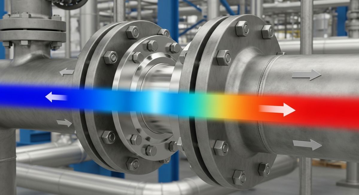
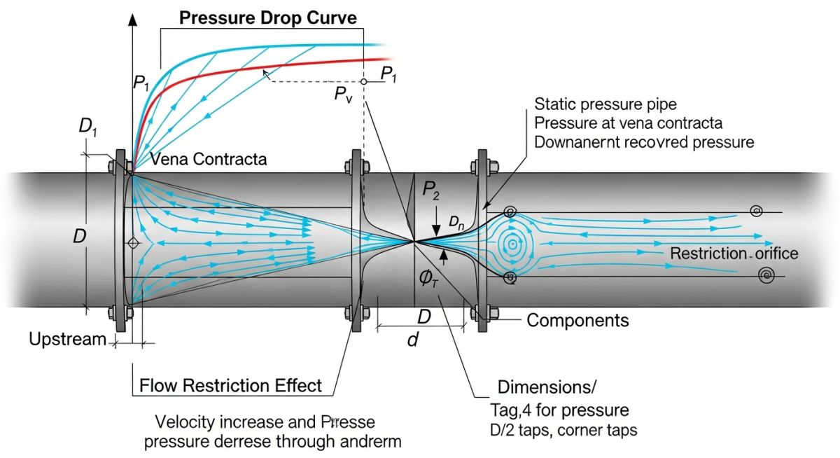
To understand how a restriction orifice works, we must look at Bernoulli’s principle and the conservation of energy. When a fluid passes through a restricted bore, its velocity increases significantly. This increase in kinetic energy comes at the expense of static pressure. The point of maximum velocity and minimum static pressure is known as the vena contracta, which occurs slightly downstream of the physical orifice plate.
As the fluid exits the orifice and expands into the full pipe diameter, high turbulence and frictional drag convert a large portion of that kinetic energy into thermal energy and noise. This results in a permanent pressure loss. Unlike a venturi tube or a flow nozzle, which are designed to recover static pressure downstream, a restriction orifice is designed to maximize this permanent pressure loss.
The Sizing Equations and Physics
For liquid systems, the sizing of a restriction orifice is governed by the standard square-root relationship between flow rate and pressure drop. The basic equation for liquid flow through an orifice is:
Where:
Q = Volumetric flow rate (m³/s)
Cd = Discharge coefficient (typically 0.6 to 0.62 for square-edged restriction plates)
A = Area of the orifice bore (m²)
delta_P = Permanent pressure drop across the plate (Pa)
rho = Fluid density (kg/m³)
For gas and vapor systems, the sizing becomes significantly more complex due to compressibility effects. As the pressure drop across the plate increases, the gas velocity increases. If the downstream pressure drops below a critical threshold, the velocity at the orifice bore reaches the speed of sound (Mach 1). This condition is known as choked flow.
What are the Primary Restriction Orifice Types?
Depending on the process conditions, a single-stage plate may not be sufficient. In my practice, I classify restriction orifices into four primary types based on their mechanical design and application limits:
- Single-Stage Restriction Orifice (SSRO): A single plate clamped between flanges. It is highly cost-effective but limited to low-to-moderate pressure drops where cavitation, flashing, or choked flow are not risks.
- Multi-Stage Restriction Orifice (MSRO): An assembly consisting of multiple plates arranged in series within a spool piece. This design divides the total pressure drop across several stages, ensuring that no single stage exceeds the critical pressure ratio or triggers cavitation.
- Conical Entrance Orifice: Designed with a beveled inlet to handle highly viscous fluids or fluids containing small suspended solids, preventing erosion at the inlet edge.
- Multi-Bore Restriction Orifice: A single plate featuring multiple smaller holes instead of one central bore. This design significantly reduces high-frequency acoustic noise by shifting the peak frequency of the noise generated to a range that is easily dampened by the pipe wall.
Selecting the correct restriction orifice configuration requires analyzing the process fluid state, pressure drop ratio, and potential noise generation. The table below outlines the standard selection criteria used in major EPC projects.
| Orifice Type | Max Pressure Drop (Liquid) | Max Pressure Drop (Gas) | Noise Limit Compliance | Primary Application |
|---|---|---|---|---|
| Single-Stage (SSRO) | < 10 bar | Pressure Ratio < Critical | Up to 85 dBA | Pump minimum flow bypass, line balance |
| Multi-Stage (MSRO) | No limit (staged) | No limit (staged) | Up to 110 dBA (dampened) | High-pressure blowdown, boiler feedwater bypass |
| Multi-Bore Plate | < 15 bar | Pressure Ratio < Critical | Reduces noise by 10-15 dBA | Steam vents, gas depressurization near work areas |
Technical Mapping & Specifications Matrix
To ensure compliance with international design codes, engineers must map physical parameters to the correct standards. The matrix below provides the direct references required for mechanical design.
| Parameter | Acronym | Standard Reference | Design Significance |
|---|---|---|---|
| Beta Ratio | d/D | ISO 5167-2 | Ratio of bore diameter to pipe inner diameter. Must be between 0.2 and 0.75. |
| Pressure Piping Code | ASME B31.3 | ASME B31.3 | Governs the minimum plate thickness to prevent mechanical bending under differential pressure. |
| Flange Standards | ASME B16.5 / B16.47 | ASME B16.5 | Governs the pressure-temperature ratings of the flanges holding the plate. |
How to Verify Restriction Orifice Site Installation?
During my time on construction sites, I have witnessed several instances where restriction plates were installed backward, or worse, the wrong plate was installed in the wrong line. Because these plates look identical from the outside once bolted between flanges, strict field verification is mandatory before the system is pressurized.
Pre-Commissioning Checklist
Field Case Study: Mitigating Cavitation in a Pump Bypass Line
The Problem: Severe Vibration and Pipe Thinning
At a petrochemical refinery in 2019, a high-pressure boiler feedwater pump bypass line was experiencing severe vibration and high-frequency noise (measured at 104 dBA). The system utilized a single-stage restriction orifice to drop pressure from 120 bar down to 10 bar. Within six months of operation, the downstream piping experienced localized wall thinning due to severe cavitation, leading to a pinhole leak and an unscheduled shutdown.
The Solution: Multi-Stage Pressure Reduction
I was called in to analyze the system. The cavitation index calculation revealed that the single-stage drop was forcing the fluid pressure far below its vapor pressure at the vena contracta. To resolve this, we replaced the single-stage plate with a 5-stage restriction orifice spool piece. This stepped the pressure down gradually (120 bar to 95 bar, to 70 bar, to 48 bar, to 28 bar, and finally to 10 bar), keeping the fluid pressure well above its vapor pressure at every stage.
The Outcome: The noise level dropped from 104 dBA to a safe 78 dBA, well within OSHA limits. Subsequent ultrasonic thickness testing of the downstream piping over the next three years showed zero wall thinning, proving that the cavitation had been completely eliminated.
Frequently Asked Engineering Questions
What is the difference between a restriction orifice and a flow orifice?
How do you prevent cavitation in a restriction orifice?
What is the typical discharge coefficient (Cd) used for sizing?
When should a multi-stage restriction orifice be used instead of a single-stage?
What materials are commonly used for restriction orifices?
How does choked flow affect restriction orifice sizing?
Complete Course on
Piping Engineering
Check Now
Key Features
- 125+ Hours Content
- 500+ Recorded Lectures
- 20+ Years Exp.
- Lifetime Access
Coverage
- Codes & Standards
- Layouts & Design
- Material Eng.
- Stress Analysis

📚 Recommended Resources: Restriction Orifice
Related posts:
![An engineer performing an API 579 fitness for service assessment on an industrial pressure vessel.]()
How to Perform API 579 Fitness for Service Assessment
![3D CAD render of a bolted flange joint assembly showing a compressed gasket.]()
Understanding Gasket m and y Factors in Flange Design
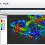
![PASS/START-PROF 4.86 pipe stress analysis software interface displaying a 3D piping model.]()
PASS/START-PROF 4.86 Released: Discover the New Pipe Stress Analysis Capabilities
![ASME certification mark stamped on an industrial pressure vessel nameplate]()
What is ASME Certification? Procedure and Mark Explained
![Professional technician inserting a high-pressure hydro jetting nozzle into a sewer pipe cleanout.]()
What is Hydro Jetting and How Does It Work?
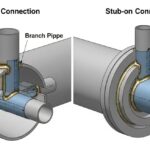
![Side-by-side comparison diagram of stub-in and stub-on piping branch connections.]()
Stub-in vs Stub-on Piping Connections: Engineering Design Guide