Refinery Storage Tanks: Engineering Principles, API Standards & Selection Guide

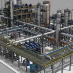
Figure 1: Modern refinery tank farm layout compliant with NFPA 30 spacing.
Refinery Storage Tanks are the critical cardiovascular system of any downstream facility, serving as the primary buffer between incoming crude oil feedstocks and outgoing refined products. Unlike simple containment vessels, these atmospheric storage units are complex engineering systems designed to handle volatile hydrocarbons while mitigating emission losses and fire risks. Whether utilizing a fixed roof vs external floating roof design, the integrity of these assets relies heavily on strict adherence to API 650 tank design standards and rigorous lifecycle management.
Core Definition
A Refinery Storage Tank is a large container, usually cylindrical and constructed of steel, designed to store liquids or gases at or near atmospheric pressure. They are categorized by their roof design (Fixed, Floating, or Geodesic Dome) and are governed by codes such as API 650 for construction and API 653 for inspection.
Quick Navigation
Test Your Knowledge: Tank Engineering
Complete Course on
Piping Engineering
Check Now
Key Features
- 125+ Hours Content
- 500+ Recorded Lectures
- 20+ Years Exp.
- Lifetime Access
Coverage
- Codes & Standards
- Layouts & Design
- Material Eng.
- Stress Analysis
1. Engineering Theory & API Design Standards
The structural integrity of Refinery Storage Tanks is not merely a matter of plate thickness; it is a complex interaction between hydrostatic pressure, wind loads, seismic activity, and soil bearing capacity. The global hydrocarbon industry relies almost exclusively on the API 650 tank design standards for atmospheric storage. Unlike pressure vessels (ASME VIII), these tanks operate at pressures ranging from atmospheric to slightly above (up to 2.5 PSI if designed per API 620).
When selecting a design code, engineers must differentiate between construction, low-pressure storage, and in-service inspection. The hierarchy of standards ensures that every Refinery Storage Tank maintains containment integrity throughout its 30+ year lifecycle.
| Standard Code | Full Title | Primary Application |
|---|---|---|
| API 650 | Welded Tanks for Oil Storage | New construction of atmospheric tanks (Internal pressure < 2.5 PSI). |
| API 620 | Design & Construction of Large, Welded, Low-Pressure Storage Tanks | Cryogenic (LNG) or higher pressure applications (up to 15 PSI). |
| API 653 | Tank Inspection, Repair, Alteration, and Reconstruction | In-service maintenance, patch plating, and integrity assessment. |
Table 1: The “Big Three” API Standards governing Refinery Storage Tanks.
🧮 Engineering Math: Shell Thickness Calculation
Per API 650 tank design standards (1-Foot Method), the required shell thickness at any specific course is calculated based on the hydrostatic head of the liquid. The formula for Design Shell Thickness (td) is:
- td: Design Shell Thickness (mm)
- D: Nominal Tank Diameter (m)
- H: Design Liquid Level (m)
- G: Specific Gravity of the liquid (e.g., 0.85 for Crude)
- Sd: Allowable Stress for Design Condition (MPa)
- CA: Corrosion Allowance (mm)
2. Tank Types: Fixed vs. Floating Roof Selection
Choosing the correct architecture for Refinery Storage Tanks depends heavily on the vapor pressure of the stored product (TVP). The primary design decision typically revolves around a Fixed roof vs external floating roof configuration.
The Floating Roof Mechanism
For volatile products like Gasoline, Naphtha, or Crude Oil, a floating roof is mandatory to reduce evaporation losses and prevent the formation of an explosive vapor cloud. The Floating roof tank mechanism relies on a pontoon or double-deck structure that floats directly on the liquid surface, rising and falling with the product level.
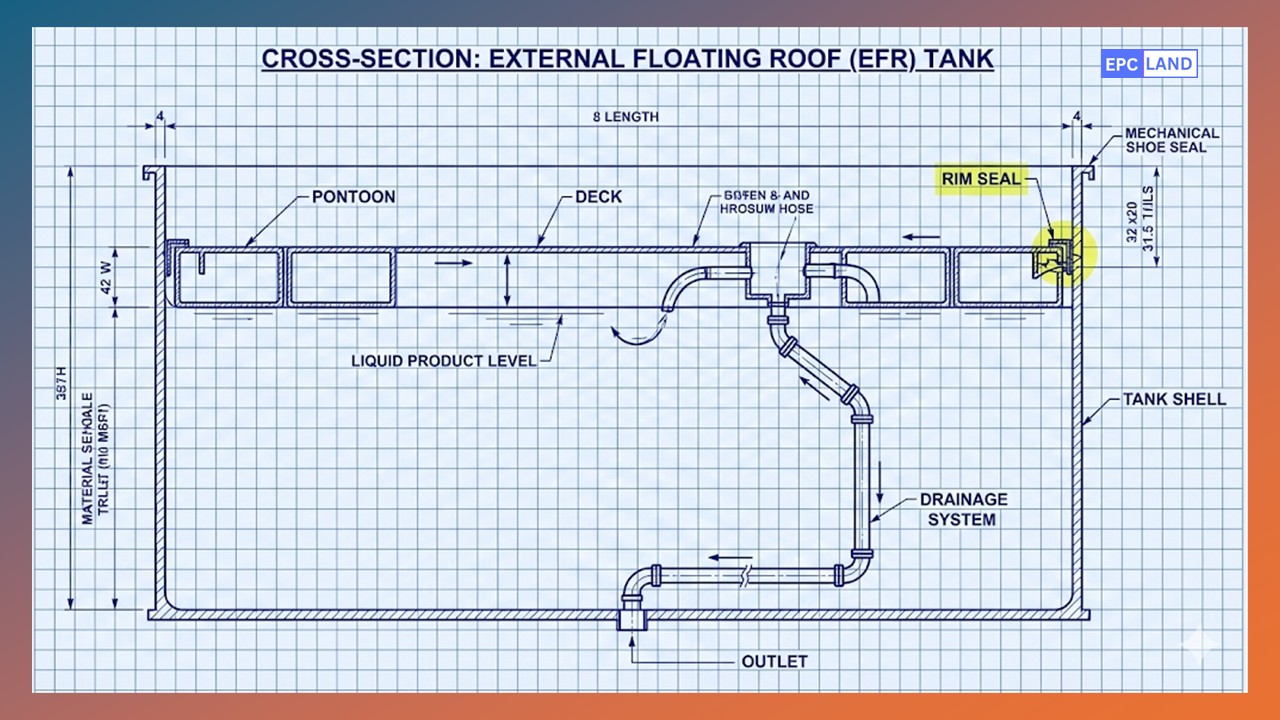
Figure 2: Components of an External Floating Roof (EFR) Tank including Primary and Secondary Seals.
The critical component in this mechanism is the Rim Seal. Since the roof must move freely inside the shell, a gap exists between the roof edge and the tank wall. Mechanical shoe seals or liquid-filled tube seals are installed in this gap to prevent vapor leakage. Failure of this seal is a leading cause of rim fires.
Fixed Roof (Cone/Dome)
- Best for: Diesel, Fuel Oil, Bitumen (Low volatility).
- Pros: Lower construction cost, protects product from rain/snow completely.
- Cons: Requires Vapor Recovery Unit (VRU) for volatile liquids; breathing losses are high.
External Floating Roof (EFR)
- Best for: Crude Oil, Gasoline, Jet Fuel.
- Pros: Minimizes evaporation by >90%; reduces fire risk.
- Cons: High maintenance on seals; rain water must be drained from the roof via flexible pipes.
Tank Farm Layout & Safety Distances
Safety in a refinery setting begins with layout. Engineers must strictly adhere to tank farm safety distances outlined in NFPA 30 and IP 19. These codes dictate the minimum spacing between adjacent tanks (Shell-to-Shell) and between tanks and property lines to prevent a “domino effect” during a fire.
Typically, for floating roof tanks, the minimum spacing is 0.5 × Diameter of the adjacent tank. Additionally, the containment dyke (bund wall) must be sized to hold 110% of the largest tank’s volume to capture spills, preventing hazardous runoff.
Case Study: Soil-Side Bottom Plate Corrosion in a 25-Year-Old Crude Tank
One of the most insidious failure modes in Refinery Storage Tanks is underside corrosion, which often goes undetected until a leak occurs. This case study details the investigation and repair of a catastrophic storage tank bottom corrosion event at a coastal refinery, guided by strict API 653 protocols.
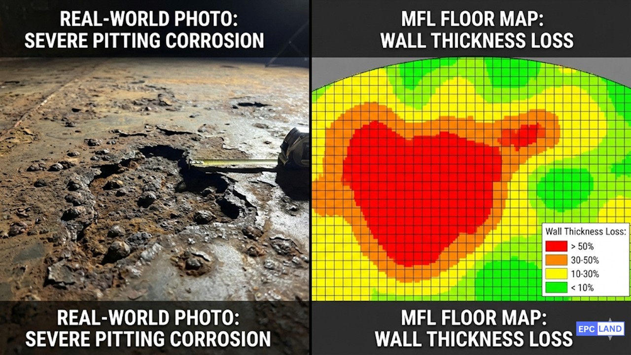
Figure 3: Left: Actual pitting observed after blasting. Right: MFL color-map indicating areas of < 4mm remaining thickness (Red Zones).
Asset Data & Conditions
Equipment Tag:
TK-402 (External Floating Roof)
Service:
Sour Crude Oil (High Sulfur)
Dimensions:
Dia: 60m | Height: 18m | Cap: 50,000 m³
Last Inspection:
12 Years Prior
The Failure Mode
During routine groundwater monitoring, traces of hydrocarbons were detected in the observation wells surrounding the tank dyke. The tank was immediately taken out of service, drained, and cleaned for entry.
The maintenance team deployed an API 653 inspection checklist, starting with a Magnetic Flux Leakage (MFL) floor scan. The data revealed widespread “soil-side” corrosion.
Root Cause Analysis (RCA): The bitumen sand layer beneath the tank had degraded, allowing moisture ingress. The presence of Sulfate-Reducing Bacteria (SRB) in the soil created an acidic environment, leading to rapid localized pitting. The original Cathodic Protection (CP) system had failed 5 years prior and was never repaired, leaving the bottom plates indefensible against the corrosive soil.
Engineering Solution & ROI
Given that the remaining thickness in 40% of the plates was below the minimum required thickness (tmin) calculated per API 653, a simple patch repair was deemed insufficient for a 20-year run life.
- 1 Annular Plate Replacement: The critical annular plates (which support the shell load) were cut out and replaced with thicker, impact-tested steel to meet current seismic codes.
- 2 Double Bottom Retrofit: Instead of removing the old floor entirely, a High-Density Polyethylene (HDPE) liner was laid over the old floor, followed by a new sand layer and a new steel bottom. This effectively created a double-bottom tank with leak detection capability.
- 3 CP Upgrade: A new Impressed Current Cathodic Protection (ICCP) system was installed between the old and new floors.
EPCLand YouTube Channel
2,500+ Videos • Daily Updates
4. Frequently Asked Questions (FAQ)
What is the difference between API 650 and API 653?
Why are Floating Roofs preferred for crude oil storage?
How often should an API 653 inspection be performed?
What are the safety distance requirements for tank farms?
Final Engineering Note
Mastering Refinery Storage Tanks requires a holistic view—from the initial API 650 calculation sheets to the daily operational checks of rim seals. As environmental regulations tighten in 2026, the industry is shifting toward more robust leak detection and double-bottom retrofits. Ensuring asset integrity is not just about compliance; it is the first line of defense in process safety management.
Retake Knowledge Quiz
Related posts:
![Outdoor pipeline block valve station with large isolation valves and actuators.]()
What are Pipeline Block Valves and How to Design Stations
![3D CAD model of an industrial process plant showing equipment clearances and access platforms.]()
A Guide to Plant Clearances and Access Requirements
![Engineering technical bid evaluation spreadsheet comparing vendor specifications and compliance metrics.]()
How to Master Technical Bid Evaluation for Complex Engineering Procurement
![Large-diameter steel pipes with protective blue anti-corrosive epoxy coating stacked in an industrial facility.]()
Protecting Steel Pipes with Anti-Corrosive Steel Pipe Coatings
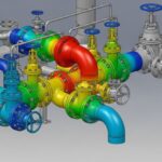
![3D CAD model of industrial piping showing stress intensification factor heatmaps at elbows and tees.]()
Why Stress Intensification Factor in Piping Dictates Fatigue Life
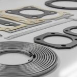
![A collection of different industrial pipe flange gaskets on a workbench]()
How to Select the Best Pipe Flange Gaskets for Piping Systems