Mastering Reboiler Control Systems: Engineering Best Practices for 2026
You are in the control room during a winter startup, and the distillation column pressure refuses to stabilize. The reboiler is oscillating wildly, causing tray flooding and off-spec product. You suspect the condensate valve is sticking, but the real culprit is likely the fundamental architecture of your Reboiler Control Systems. Choosing between steam throttling and condensate flooding isn’t just a design choice; it is the difference between a steady-state operation and a maintenance nightmare. This guide provides the technical blueprint to ensure your heat transfer remains precise, predictable, and profitable.
Key Engineering Takeaways
- Identify why downstream condensate control is superior for preventing “hammering” in most Reboiler Control Systems.
- Master the 2026 standards for loop seal sizing to maintain liquid level stability without vapor bypass.
- Compare sensible heat vs. condensing fluid response times for optimized PID tuning.
What is the most effective Reboiler Control System?
The most effective Reboiler Control Systems utilize condensate throttling (placing the control valve downstream). This method regulates the heat transfer area by “flooding” the tubes with liquid, providing a more stable and linear response compared to upstream steam throttling, which can cause erratic pressure drops and vacuum issues within the exchanger shell.
“In my 20 years on-site, I’ve seen more reboilers fail due to improper valve placement than actual mechanical fatigue. If your Reboiler Control Systems don’t account for the latent heat of condensation properly, you’re fighting a losing battle against physics.”
— Atul Singla, Founder of EPCLand
In This Guide
Complete Course on
Piping Engineering
Check Now
Key Features
- 125+ Hours Content
- 500+ Recorded Lectures
- 20+ Years Exp.
- Lifetime Access
Coverage
- Codes & Standards
- Layouts & Design
- Material Eng.
- Stress Analysis
Knowledge Check: Reboiler Control Systems
Test your engineering expertise on 2026 standards.
1. Why is downstream condensate throttling often preferred in Reboiler Control Systems over upstream steam throttling?
Fundamental Mechanics of Reboiler Control Systems
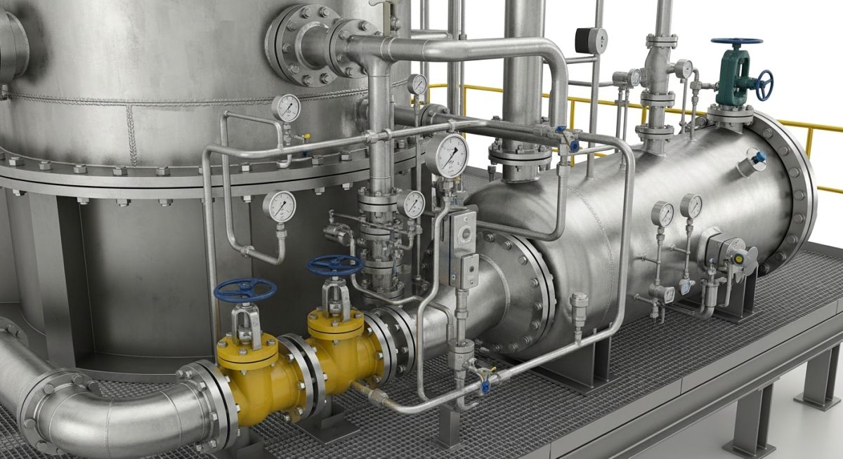
At its core, the performance of Reboiler Control Systems hinges on the delicate balance between the heat duty required by the distillation column and the latent or sensible heat provided by the utility medium. In modern process plants, the reboiler acts as the “engine” of the separation process, where any fluctuation in vapor rate directly impacts product purity and column pressure stability. Engineering these systems requires a deep understanding of heat transfer coefficients and the physical dynamics of phase change. According to the American Institute of Chemical Engineers (AIChE), improper control logic in heat exchangers is a leading cause of operational cycling and energy waste in 2026 industrial facilities.
The primary objective of Reboiler Control Systems is to regulate the “Boil-up” rate. This is typically achieved by manipulating the flow of the heating medium—usually steam, hot oil, or process streams—to maintain a target temperature at a specific tray or a desired vapor-to-liquid ratio. Engineers must account for the “thermal lag” inherent in the system; the time it takes for a valve adjustment to manifest as a temperature change in the column can range from seconds to several minutes, depending on the volume of the reboiler sump and the heat transfer area.
Reboiling with a Condensing Fluid: Precision Strategies
When using steam or other condensing vapors, Reboiler Control Systems utilize the latent heat of vaporization, which offers significantly higher energy density than sensible heat. However, this introduces the complexity of condensate management. In 2026, the industry has shifted toward high-precision modulation where the focus is not just on the inlet pressure, but on the effective wetted surface area within the exchanger shell.
One common strategy is “Steam Throttling,” where the control valve is placed on the vapor inlet. While intuitive, this method can lead to “stalling” if the pressure inside the exchanger drops below the condensate header pressure. A more robust approach often integrated into Reboiler Control Systems involves varying the liquid level within the exchanger. By flooding the tubes with condensate, the active heat transfer area is reduced, allowing for extremely fine control over the heat duty without the risk of vacuum formation or erratic pressure swings.
Furthermore, effective Reboiler Control Systems must incorporate non-condensable venting. Accumulation of air or carbon dioxide can “blanket” the heat transfer surfaces, causing a deceptive drop in performance that operators often mistake for valve failure. Modern 2026 designs utilize automated thermostatic vents to ensure that only pure vapor occupies the heat transfer zone, maintaining the integrity of the control loop.
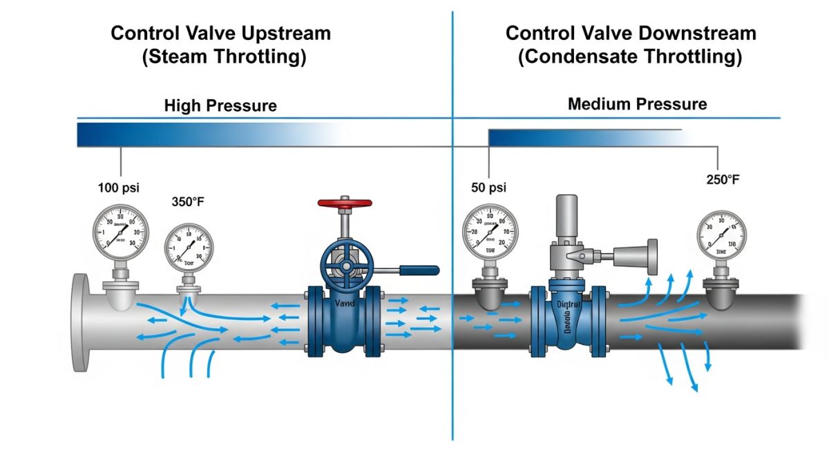
Optimizing Reboiler Control Systems: Upstream vs Downstream Valve Location
The debate between placing the control valve on the steam inlet (upstream) versus the condensate outlet (downstream) is central to the design of Reboiler Control Systems. Upstream throttling regulates the pressure and saturation temperature of the steam. While this provides a rapid response, it often leads to “condensate stall”—a condition where the exchanger pressure drops below the return header pressure, causing liquid to back up and heat transfer to plummet. In 2026, engineers increasingly favor downstream “flooding” control for its inherent stability and linearity.
| Feature | Upstream (Steam Side) | Downstream (Condensate Side) |
|---|---|---|
| Control Variable | Steam Pressure/Temperature | Effective Heat Transfer Area |
| Response Speed | Fast (Seconds) | Moderate (Minutes) |
| Equipment Risk | Vacuum/Stall Potential | Corrosion at Air-Liquid Interface |
| Valve Size | Large (Vapor Volume) | Small (Liquid Volume) |
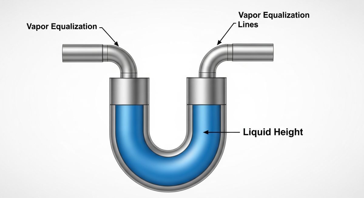
The Role of Loop Seals in Reboiler Control Systems
To prevent vapor from bypassing the exchanger and entering the condensate return system—a phenomenon known as “live steam blow-through”—modern Reboiler Control Systems utilize a loop seal or a dedicated level pot. These mechanical configurations ensure a constant liquid head is maintained, providing a hydraulic barrier. According to the American Society of Mechanical Engineers (ASME) Section VIII standards, the design of these piping loops must account for the maximum possible pressure differential to prevent seal rupture during process upsets.
Managing Reboiler Control Systems with Sensible Heat Sources
When the heating medium is a single-phase fluid like hot oil or a process stream, Reboiler Control Systems rely on sensible heat transfer (Q = mCpΔT). Unlike condensing fluids, the heat duty is controlled by manipulating the mass flow rate (m) or the bypass ratio. In 2026, the use of 3-way diverting valves is the gold standard for these applications. This ensures that the total flow through the main utility header remains constant, preventing hydraulic surges in the plant-wide heating loop while precisely modulating the portion of flow entering the reboiler.
Safety and Logic for Direct-Fired Reboiler Control Systems
Direct-fired Reboiler Control Systems are the most complex due to the inherent risks of combustion. These systems must comply with API Standard 560 for fired heaters. Control logic here is “constraint-based”: while the primary loop maintains process temperature, secondary override loops monitor tube skin temperatures and stack oxygen levels. If the flame pattern becomes erratic or a tube “hot spot” is detected, the Burner Management System (BMS) must take precedence over the process control loop to trigger an emergency shutdown (ESD).
Reboiler Heat Duty & Valve Sizing Calculator
Estimate the required steam flow and approximate valve Cv for your Reboiler Control Systems based on 2026 efficiency standards.
Note: Calculations assume saturated steam latent heat and a linear valve characteristic. For downstream Reboiler Control Systems, valve Cv will be significantly lower due to liquid phase handling.
Case Study: Solving Pressure Oscillations in a C3 Splitter
The Problem
A Propane-Propylene (C3) splitter experienced +/- 5% pressure swings. The existing Reboiler Control Systems used upstream steam throttling, causing “condensate hammer” and erratic heat transfer.
The Solution
The engineering team bypassed the upstream valve and installed a high-precision globe valve on the condensate return line, effectively converting to “Flooding Control” with a 2-meter loop seal.
The Result
Column pressure stabilized within 0.2% of setpoint. Steam consumption dropped by 4% due to the elimination of sub-cooling losses inherent in the old Reboiler Control Systems.
Technical Breakdown: The Loop Seal Logic
The critical success factor in this retrofit was the Equalization Line. Without it, the loop seal would have suffered from vapor binding, causing the condensate to “slug” through the system. By piping the top of the level pot back to the reboiler shell, the team ensured that the pressure differential across the control valve remained strictly a function of the liquid head.
This modification aligns with API RP 551 guidelines for process instrumentation, proving that even legacy Reboiler Control Systems can be brought to 2026 efficiency standards with minor piping reconfigurations.
EPCLand YouTube Channel
2,500+ Videos • Daily Updates
Expert Insights: Lessons from 20 years in the field
Beware the Air: Many Reboiler Control Systems fail not because of the PID tuning, but due to non-condensable gas buildup. Always install a thermostatic air vent at the highest point of the steam chest. Even 1% air can reduce the heat transfer coefficient by over 50%.
Valve Characteristic Choice: For condensate throttling, always specify an “Equal Percentage” valve. Since the relationship between flooded area and heat duty is non-linear, the equal-percentage curve helps linearize the overall loop response in complex Reboiler Control Systems.
Sub-cooling Risks: While flooding control is stable, it causes condensate sub-cooling. If your process fluid is sensitive to localized cold spots (which can cause fouling or crystallization), you may need a bypass or a hybrid strategy to maintain a minimum wall temperature.
References & Standards
- ASME Section VIII: Rules for Construction of Pressure Vessels – Governing standards for reboiler shell and tube design.
- API Standard 560: Fired Heaters for General Refinery Service – Safety and control benchmarks for direct-fired Reboiler Control Systems.
- API RP 551: Process Measurement Instrumentation – Recommended practices for control valve and transmitter placement.
- ISO 13706: Air-cooled heat exchangers – Standards often referenced when designing reboiler auxiliary cooling and venting.
Reboiler Control Systems: Frequently Asked Questions
What is the difference between steam side and condensate side control in Reboiler Control Systems?
Why does my reboiler oscillate even when the PID loop is tuned correctly?
How do non-condensables affect Reboiler Control Systems?
Should I use a 2-way or 3-way valve for hot oil reboiler control?
What safety codes govern Direct-Fired Reboiler Control Systems?
What is the “Stall” phenomenon in Reboiler Control Systems?
📚 Recommended Resources: Reboiler Control Systems
Read these Guides


Related posts:
![High-grade industrial Wing Nut Types and Applications for mechanical assemblies.]()
Wing Nut Types and Applications: The 2026 Engineering Guide
![Industrial Monorail Crane Systems installed in a modern manufacturing plant 2026.]()
Monorail Crane Systems: Design, Types & 2026 Standards Guide
![Lead engineer performing a Factory Acceptance Test FAT on an industrial skid system 2026]()
Factory Acceptance Test FAT: The 2026 Engineering Guide to Zero-Defect Delivery
![Professional engineering workspace showing a Basis of Design document layout for a 2026 project.]()
Basis of Design: How to Write a BOD for Engineering Projects in 2026
![Industrial Flare Knockout Drum Sizing and installation in a refinery relief system.]()
Flare Knockout Drum Sizing: Design & API 521 Standards (2026 Guide)
![Industrial engineering setup showing what is a coalescer vessel in a refinery.]()
What is a Coalescer? Its Types, Working, and Applications (2026 Guide)


