Pump Shutoff Pressure: Calculation & Dead Head Safety
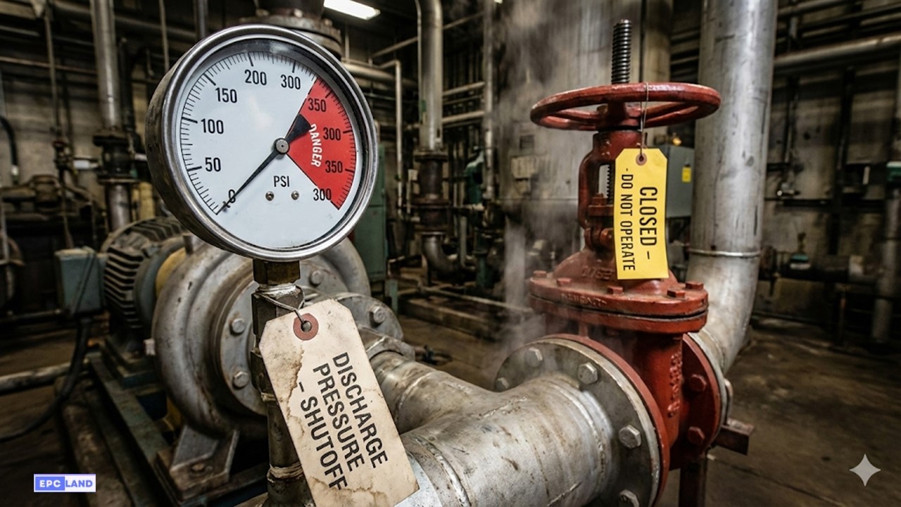
At Zero Flow, the pump generates its maximum potential pressure—known as Shutoff Pressure.
Pump Shutoff Pressure is the maximum pressure a centrifugal pump can generate when it is operating at its rated speed with the discharge valve completely closed (Zero Flow). Understanding this value is critical for two reasons: it dictates the safety rating of your piping (ASME B31.3) to prevent bursts, and it warns operators of the dangerous condition known as “Dead Heading,” which, if ignored for even a few minutes, can turn a pump into a hydraulic grenade.
Definition: Shutoff Head
Shutoff Head is the specific point on a centrifugal pump characteristic curve where the flow rate (Q) is zero and the Head (H) is at its peak.
Quick Navigation
Test Your Hydraulics IQ
Do you understand the relationship between Head, Flow, and Pressure?
Loading Question…
Explanation:
Complete Course on
Piping Engineering
Check Now
Key Features
- 125+ Hours Content
- 500+ Recorded Lectures
- 20+ Years Exp.
- Lifetime Access
Coverage
- Codes & Standards
- Layouts & Design
- Material Eng.
- Stress Analysis
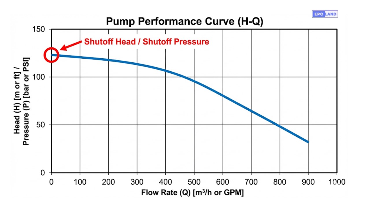
Reading the Pump Performance Curve
To find the Pump Shutoff Pressure, you do not need a calculator; you need the manufacturer’s data sheet. Every centrifugal pump comes with a centrifugal pump characteristic curve that plots Total Dynamic Head (Y-axis) against Flow Rate (X-axis).
The Shutoff Head is the point where the curve intersects the vertical Y-axis. At this specific point, the Flow Rate is Zero.
The Shutoff Head Formula
Engineers often confuse “Head” (energy) with “Pressure” (force). The pump curve gives you Head in meters or feet. To find the actual Zero Flow Pressure on your gauge, you must convert it based on the fluid’s density. Furthermore, you must understand the relationship of discharge pressure vs suction pressure.
Formula 1: Calculating Final Gauge Pressure
- Pshutoff = Final Discharge Pressure (PSI)
- H = Shutoff Head from Curve (Feet)
- SG = Specific Gravity (Water = 1.0)
- Psuction = Incoming Suction Pressure (PSI)
*CRITICAL: The curve only shows what the pump ADDS. You must add the suction pressure to get the total shutoff pressure reading.
Affinity Laws Calculation
What if you increase the pump speed using a Variable Frequency Drive (VFD)? The Pump Shutoff Pressure does not increase linearly; it increases by the square of the speed change. This is a vital check for shutoff head calculation formula verification.
Formula 2: Speed Change Impact
- H2 = New Shutoff Head
- H1 = Original Shutoff Head
- N2 = New Speed (RPM)
- N1 = Old Speed (RPM)
The Dangers of Dead Heading
Centrifugal Pump Dead Heading occurs when the pump operates at the Shutoff Point (Zero Flow) for an extended period. This usually happens when a discharge valve is left closed or a check valve fails to open. This falls under the critical category of pump deadhead protection.
| Phenomenon | Mechanism | Consequence |
|---|---|---|
| Hydraulic Churning | The impeller spins the same volume of liquid repeatedly. Friction adds energy to the fluid. | Rapid temperature rise (Water boils to steam). |
| Radial Thrust | At zero flow, hydraulic forces become unbalanced, often exceeding API 610 vibration limits. | Shaft deflection, bearing failure, and seal leaks. |
| Vaporization | Liquid turns to gas, losing its lubrication properties. | Mechanical seals run dry and shatter (Thermal Shock). |
Unlike Positive Displacement pumps, which will burst the pipe immediately if dead-headed, a centrifugal pump will simply sit there and “cook” the fluid until the seal fails or the casing seizes.
Factors, Design & Testing Protocols
While the impeller diameter and motor speed are the primary drivers, several external factors influence the actual Pump Shutoff Pressure recorded in the field. Understanding these variables is key to accurate system design and troubleshooting.
1. Fluid Properties
- Specific Gravity (Density): As mentioned, heavier fluids (like brine or sulfuric acid) will generate higher gauge pressures (PSI) than water, even if the Head (feet) remains identical.
- Viscosity: Highly viscous fluids (like heavy crude oil) increase internal disk friction. This energy loss can slightly reduce the effective shutoff head compared to water performance.
2. Impeller Condition
- Trim Diameter: A pump is often supplied with a “trimmed” impeller. The shutoff pressure is directly proportional to the square of the diameter change.
- Wear Ring Clearance: As internal clearances open up due to erosion, high-pressure fluid leaks back to the suction side, lowering the observed shutoff pressure.
Critical Safety Distinction: Centrifugal vs. PD Pumps
It is dangerous to assume all pumps behave the same way at zero flow. The behavior of a Positive Displacement (PD) pump is fundamentally different and requires distinct pump deadhead protection strategies.
| Pump Type | Shutoff Behavior | Risk Level | Required Protection |
|---|---|---|---|
| Centrifugal Pump | Pressure peaks at a defined maximum (Shutoff Head) and stays there. | Moderate (Thermal Failure) | Minimum Flow Recycle Line (to prevent heating). |
| Positive Displacement (PD) | Pressure rises theoretically to infinity until the pipe bursts or motor stalls. | Critical (Explosion) | Full-flow Pressure Relief Valve (PRV) on discharge. |
| Diaphragm Pump | Stalls at the air supply pressure (pneumatic limit). | Low (Self-Limiting) | Air Regulator / Filter Regulator (FR). |
Design & Testing Protocols
1. Piping Material Selection (ASME B31.3)
In process piping design, the “Design Pressure” of the downstream piping must usually be set at or above the Pump Shutoff Pressure. For example, if your normal operating pressure is 100 PSI but the Shutoff is 150 PSI, using Class 125 flanges (rated ~175 PSI) is safe. Using lower-rated piping relies entirely on relief valves, introducing a failure point.
2. Testing Procedure (Commissioning)
To validate system integrity, a “Shutoff Test” is often performed. Warning: Be aware of zero flow operation risks and limit the duration strictly.
- Preparation: Ensure pump is primed, suction valve is fully open, and vents are bled.
- Closure: Slowly close the discharge valve until flow hits zero (Max duration: 30 seconds).
- Measurement: Record the discharge gauge reading and the suction gauge reading.
- Calculation: Subtract Suction Pressure from Discharge Pressure. Compare this differential to the Factory Curve at Zero Flow.
- Verification: If the field reading is >5% lower than the curve, investigate for internal wear, reverse rotation, or incorrect impeller size.
EPCLand YouTube Channel
2,500+ Videos • Daily Updates
Case Study: Pump Shutoff Pressure & Thermal Failure
The most dangerous misconception about centrifugal pumps is that they can safely run against a closed valve indefinitely. While Pump Shutoff Pressure is a useful design value, operating there is destructive. In this forensic analysis, we examine a Boiler Feed Pump failure at a power plant where a simple valve error turned a centrifugal pump into a steam bomb.
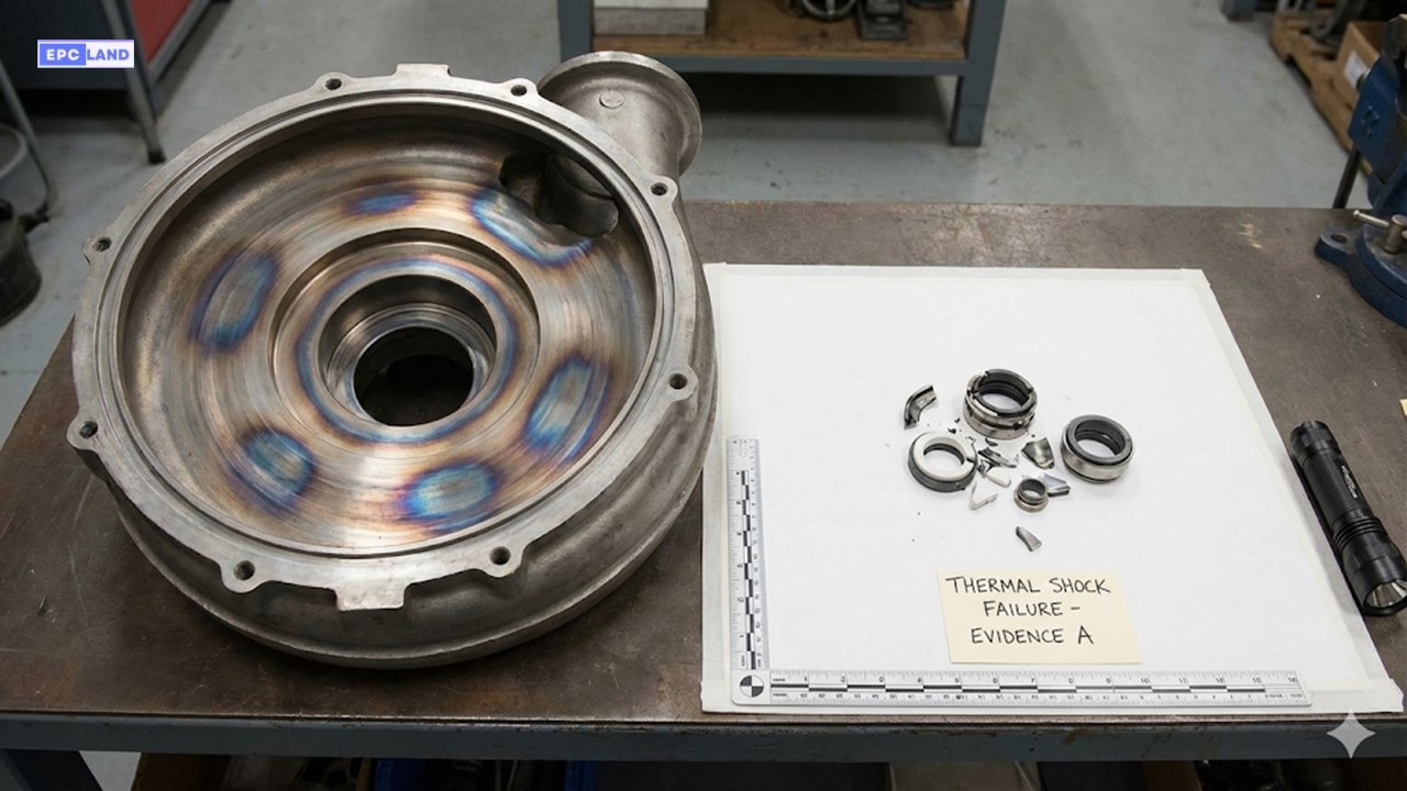
Figure 2: Heat tinting (purple discoloration) on the volute and shattered seal faces caused by fluid vaporization.
Project Data
Location
Thermal Power Station, Ohio, USA
Equipment
P-401 (Multistage Boiler Feed Pump)
Motor Power
450 kW (Running at 3560 RPM)
Failure Mode
Dead Heading / Vaporization
The Incident: 45 Minutes to Failure
During a post-maintenance startup, the operator energized the motor but forgot to open the manual discharge isolation valve. The automatic recirculation valve (ARC) was also inadvertantly blocked. The pump ran at Pump Shutoff Pressure for approximately 45 minutes.
The Physics of Failure:
1. Energy Trap: The 450 kW motor continued to input energy into the water. Since there was Zero Flow, none of this energy left the system as hydraulic work. It was all converted into friction and heat.
2. Temperature Rise: The water temperature inside the casing rose at a rate of roughly 10°C per minute. Within 20 minutes, it exceeded 200°C (392°F).
3. Vaporization & Seizure: The water flashed into high-pressure steam. Steam provides no lubrication/cooling for the mechanical seals. The faces ran dry and shattered. Simultaneously, the rotating wear rings contacted the stationary casing due to thermal expansion, seizing the shaft instantly.
Engineering Solution: Minimum Flow Protection
The root cause was the lack of a flow path to dissipate heat. The plant retrofitted the system to ensure Minimum Continuous Thermal Flow (MCTF).
- Hardware Fix: Installed a dedicated Automatic Recirculation Valve (ARV) on the discharge. This mechanical valve detects low flow and automatically pops open a bypass line to send ~30% of the flow back to the suction tank.
- Logic Update: Added a “Valve Position Mismatch” trip in the DCS. If the pump is running but the discharge valve limit switch shows “Closed” for >15 seconds, the motor trips automatically.
Key Safety Rule
Centrifugal Pump Dead Heading is not a benign condition. While the pressure (Shutoff Head) is predictable, the temperature rise is rapid and destructive. Always ensure a minimum flow bypass line is available and open during startup.
Frequently Asked Questions
Can I calculate Shutoff Head if I don’t have the pump curve?
Yes, there is an empirical Shutoff Head Formula for approximation based on impeller diameter and speed.
H = (D × N / 1840)²
Where H is Head in feet, D is Impeller Diameter in inches, and N is Speed in RPM.
Note: This is an estimation. Always verify with the OEM curve for critical safety limits.
Do Positive Displacement (PD) pumps have a Shutoff Pressure?
NO. This is a dangerous distinction. A centrifugal pump has a maximum hydraulic limit (Shutoff Head). A Positive Displacement pump (like a piston or gear pump) will theoretically build infinite pressure until the pipe bursts, the motor stalls, or the shaft snaps. You must NEVER attempt to find the “Shutoff Pressure” of a PD pump; it relies entirely on a Pressure Relief Valve (PRV) for safety.
Is it safe to run a pump at Shutoff Pressure for testing?
Briefly, yes. Maintenance teams often perform a “Shutoff Head Test” to check for internal wear (impeller/wear ring clearance). If the measured Zero Flow Pressure is significantly lower than the factory curve, the internal clearances have likely opened up. However, this test should be limited to less than 60 seconds to avoid thermal buildup.
Does Shutoff Pressure change with fluid density?
The Shutoff Head (in meters/feet) remains constant regardless of the fluid. However, the Shutoff Pressure (in PSI/Bar) changes directly with Specific Gravity. Pumping sulfuric acid (SG 1.8) will generate nearly double the gauge pressure at shutoff compared to pumping water, even though the head is identical.
Final Thoughts for 2026
Pump Shutoff Pressure is a double-edged sword. It dictates the mechanical integrity required for your piping design, but it also defines the danger zone for your operations. As we move into 2026, smart sensors and “Active Power Monitoring” are becoming standard to detect low-flow conditions, but understanding the raw physics of the Pump Performance Curve remains the engineer’s best defense against failure.

Related posts:
![High-grade industrial Wing Nut Types and Applications for mechanical assemblies.]()
Wing Nut Types and Applications: The 2026 Engineering Guide
![Industrial Monorail Crane Systems installed in a modern manufacturing plant 2026.]()
Monorail Crane Systems: Design, Types & 2026 Standards Guide
![Lead engineer performing a Factory Acceptance Test FAT on an industrial skid system 2026]()
Factory Acceptance Test FAT: The 2026 Engineering Guide to Zero-Defect Delivery
![Professional engineering workspace showing a Basis of Design document layout for a 2026 project.]()
Basis of Design: How to Write a BOD for Engineering Projects in 2026
![Industrial Flare Knockout Drum Sizing and installation in a refinery relief system.]()
Flare Knockout Drum Sizing: Design & API 521 Standards (2026 Guide)
![Advanced Reboiler Control Systems in a modern petrochemical refinery 2026.]()
Reboiler Control Systems: Engineering Guide to Precision Control 2026


