Table of Contents
Pressure Transient Analysis Liquid HC Pipelines and Water Hammer Calculations
In my 20-plus years of designing liquid hydrocarbon pipelines, I have seen firsthand what happens when a simple valve closure goes wrong. I remember a project in the Middle East where a 24-inch crude oil line experienced an unscheduled emergency shutdown. The main isolation valve slammed shut in under five seconds due to an actuator calibration error. The resulting water hammer sent a shockwave back to the pump station, blowing out a flange gasket and spilling hundreds of barrels of crude. That incident drove home a lesson I never forgot: you cannot design a safe pipeline without a rigorous transient analysis.
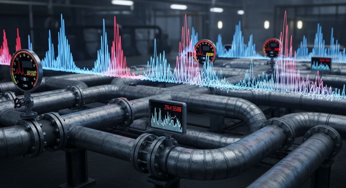
Dynamic pressure surges, commonly known as water hammer, are the silent killers of high-pressure piping systems. When the kinetic energy of a moving fluid column is abruptly halted, it transforms into a high-pressure wave that travels back and forth through the pipeline at the speed of sound. If your design does not account for these transient forces, you risk catastrophic pipe rupture, pump casing failure, and severe environmental damage.
Key Engineering Takeaways
- Understand the physical limits of your pipeline system under dynamic conditions.
- Master the Joukowsky formula to establish your worst-case surge baseline.
- Implement multi-stage valve closure profiles to naturally suppress pressure waves.
- Verify field instrument response times against your simulation models.
- Design robust surge relief systems that comply with ASME B31.4.
Complete Course on
Piping Engineering
Check Now
Key Features
- 125+ Hours Content
- 500+ Recorded Lectures
- 20+ Years Exp.
- Lifetime Access
Coverage
- Codes & Standards
- Layouts & Design
- Material Eng.
- Stress Analysis
Why Pressure Transient Analysis Liquid HC Pipelines Matters
Pipeline Surge Mitigation: The systematic assessment of transient pressure waves generated by valve closures, pump trips, or emergency shutdowns in liquid hydrocarbon systems. This analysis ensures that the maximum surge pressure does not exceed 110 percent of the pipeline’s maximum allowable operating pressure as mandated by ASME B31.4.
When designing liquid hydrocarbon pipelines, steady-state hydraulics only tell half the story. A pipeline that operates beautifully at a steady 50 bar can easily experience transient pressures exceeding 100 bar during a routine pump trip or valve closure. This is why ASME B31.4 strictly limits transient overpressure to 10% above the Maximum Allowable Operating Pressure (MAOP).
How to Calculate Water Hammer Pressures
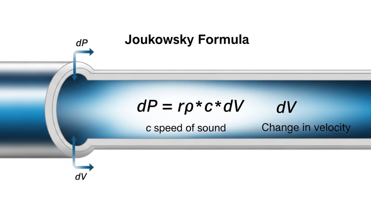
Joukowsky Equation Application: The mathematical determination of the maximum potential pressure rise resulting from an instantaneous change in fluid velocity. This calculation forms the baseline for all transient analysis and is critical for sizing surge relief systems under ASME B31.4.
The fundamental equation governing water hammer is the Joukowsky formula. It provides the maximum theoretical pressure rise (ΔP) when a fluid column is stopped instantaneously:
Where:
- ΔP is the pressure rise (Pascals, Pa)
- ρ is the fluid density (kg/m³)
- c is the speed of sound (wave speed) in the pipe-fluid system (m/s)
- Δv is the change in fluid velocity (m/s)
The wave speed (c) is not simply the speed of sound in the liquid. It is heavily influenced by the elasticity of the pipe wall. We calculate the actual wave speed using the following formula:
Where K is the bulk modulus of the liquid (Pa), E is the Young’s modulus of the pipe material (Pa), D is the pipe outer diameter (m), t is the pipe wall thickness (m), and c1 is the pipe restraint factor (typically 0.91 for fully anchored pipelines).
Step-by-Step Engineering Calculation Example
Let us calculate the transient pressure rise for a 24-inch carbon steel pipeline transporting crude oil under the following parameters:
- Crude Oil Density (ρ): 860 kg/m³
- Crude Oil Bulk Modulus (K): 1.5 × 10⁹ Pa (1.5 GPa)
- Steel Young’s Modulus (E): 2.0 × 10¹¹ Pa (200 GPa)
- Pipe Outer Diameter (D): 610 mm (0.610 m)
- Pipe Wall Thickness (t): 12.7 mm (0.0127 m)
- Pipe Restraint Factor (c1): 0.91
- Initial Velocity (v0): 2.5 m/s (reduced to 0 m/s instantaneously, so Δv = 2.5 m/s)
First, we calculate the ratio of bulk modulus to Young’s modulus:
K / E = (1.5 × 10⁹) / (2.0 × 10¹¹) = 0.0075
Next, we calculate the diameter-to-thickness ratio:
D / t = 0.610 / 0.0127 = 48.03
Now, we compute the denominator correction factor:
Denominator = 1 + (0.0075 × 48.03 × 0.91) = 1 + 0.3278 = 1.3278
We can now calculate the wave speed (c):
c = sqrt( (1.5 × 10⁹ / 860) / 1.3278 ) = sqrt( 1,744,186 / 1.3278 ) = sqrt( 1,313,591 ) = 1,146.1 m/s
Finally, we apply the Joukowsky formula to find the pressure rise (ΔP):
ΔP = 860 × 1,146.1 × 2.5 = 2,464,115 Pa = 2.46 MPa (24.6 bar)
This means an instantaneous valve closure will add 24.6 bar of pressure to your steady-state operating pressure. If your normal operating pressure is 60 bar, the total transient pressure will spike to 84.6 bar. If your pipeline’s MAOP is 75 bar, this transient exceeds the 110% limit (82.5 bar) allowed by ASME B31.4, making mitigation mandatory.
Field Warning: Vapor Cavitation Risk
Do not ignore the low-pressure waves that occur when a transient wave reflects. If the local pressure drops below the vapor pressure of the liquid hydrocarbon, vapor cavities will form. When the pressure wave reverses and these cavities collapse, they generate localized micro-jets with pressures exceeding 1000 bar. This phenomenon, known as column separation, causes rapid mechanical fatigue and pinhole leaks that are incredibly difficult to detect until a major failure occurs.
Hydrocarbon Physical Properties & Wave Speeds
The table below provides typical physical properties for common liquid hydrocarbons at 15°C and the resulting wave speeds in a standard carbon steel pipe (D/t = 50) calculated using the Joukowsky-corrected wave speed formula.
| Hydrocarbon Type | Density (kg/m³) | Bulk Modulus (GPa) | Wave Speed in Steel Pipe (m/s) | Surge Pressure per 1 m/s Change (bar) |
|---|---|---|---|---|
| Light Crude Oil | 830 | 1.40 | 1,120 | 9.30 |
| Heavy Crude Oil | 920 | 1.65 | 1,180 | 10.86 |
| Diesel Fuel | 840 | 1.50 | 1,150 | 9.66 |
| Gasoline | 740 | 1.15 | 1,030 | 7.62 |
| LPG (Propane) | 510 | 0.45 | 720 | 3.67 |
Technical Mapping & Specifications Matrix
| Parameter / Entity | Acronym | Physical Unit | Standard Reference | Engineering Significance |
|---|---|---|---|---|
| Maximum Allowable Operating Pressure | MAOP | bar / psi | ASME B31.4 | The baseline pressure limit that cannot be exceeded by more than 10% during transient events. |
| Speed of Sound (Wave Speed) | c | m/s | Joukowsky Equation | Determines how fast the pressure wave propagates and the critical time for valve closure. |
| Bulk Modulus of Elasticity | K | GPa / Pa | ASTM D5025 | Measures the compressibility of the liquid hydrocarbon; higher values yield higher surge pressures. |
| Surge Relief Setpoint | SRS | bar / psi | API RP 1115 | The pressure at which surge relief valves must open to dump fluid and protect the pipeline. |
Executing Pressure Transient Analysis Liquid HC Pipelines Safely
Transient Safety Verification: The mandatory field validation process used to verify that pipeline operating parameters match the design assumptions of the surge model. This checklist ensures that valve stroke times, relief valve setpoints, and instrumentation response times comply with API RP 1115.
In my experience, the most common cause of pipeline surge failures is a mismatch between the design office assumptions and actual field settings. A valve that was modeled to close in 30 seconds might be set to close in 10 seconds by a field technician trying to optimize operations. This checklist bridges that gap.
Pre-Commissioning Surge Safety Checklist
-
Verify Valve Closure Times: Ensure that the actual field actuator stroke time matches or exceeds the minimum safe closure time calculated in the transient model.
-
Calibrate Pressure Transmitters: Confirm that high-speed pressure transmitters are installed at critical locations and calibrated to capture transient events (minimum 100 Hz sampling rate).
-
Inspect Surge Relief Valves: Validate that surge relief valves are tested and set to open at the correct overpressure limit in accordance with API RP 1115.
-
Check Nitrogen Pre-charge: For gas-loaded surge bladder vessels, verify that the nitrogen pre-charge pressure is calibrated to the temperature-corrected design value.
-
Review Pump Trip Logic: Confirm that the emergency shutdown (ESD) logic prevents simultaneous trips of multiple pumps unless absolutely necessary, to avoid massive low-pressure waves.
Field Case Study: Real-World Application
The Problem: Terminal Valve Slam
During commissioning of a 30-inch, 120-kilometer crude oil pipeline in North Africa, an unexpected power failure caused a simultaneous trip of three mainline pumps. The sudden loss of flow generated a low-pressure wave that traveled down the line, followed by a massive high-pressure surge as the downstream terminal valves closed automatically. The transient model had not accounted for the actual closure speed of the terminal’s emergency shutdown valves, which closed in 8 seconds instead of the designed 30 seconds. This discrepancy threatened to push the pipeline pressure to 118 bar, well above the MAOP of 80 bar and exceeding the 110% ASME B31.4 limit.
The Outcome: Two-Stage Valve Closure
I was brought in to resolve the issue. We performed a rapid pressure transient analysis using the Joukowsky formula to recalculate the wave speed and maximum potential surge. By modifying the terminal valve actuators to implement a two-stage closure profile (closing the first 80% of the stroke in 40 seconds, and the remaining 20% in 20 seconds), we successfully mitigated the surge. The peak transient pressure was safely limited to 74 bar, completely eliminating the need for an expensive surge relief system and saving the operator over 1.2 million USD in capital expenditures.
This case study demonstrates that mechanical modifications are not always necessary to solve complex surge problems. Often, a smart operational change—such as tuning valve closure profiles—can keep your system well within safe limits while saving millions in capital costs.
Frequently Asked Engineering Questions
What is the Joukowsky formula and when is it applicable?
How does pipe material affect the speed of sound in transient analysis?
What is the difference between steady-state hydraulics and transient analysis?
How does ASME B31.4 govern allowable overpressure during a surge event?
Why is column separation dangerous in liquid hydrocarbon pipelines?
How do surge relief valves differ from standard thermal relief valves?

📚 Recommended Resources: Pressure Transient Analysis Liquid HC Pipelines
Related posts:
![A mechanical sucker rod pumpjack operating in an oil field at sunset]()
What is Sucker Rod Pump System in Oil Production?
![Piping material engineer reviewing technical specifications on a tablet in an industrial plant.]()
How a Piping Material Engineer Drives Industrial Project Success
![Industrial refinery plant showing various types of static equipment]()
What is Static Equipment? Types and List of Static Equipments
![Side-by-side comparison of industrial process piping and power plant steam piping systems.]()
Differences Between ASME B31.3 and B31.1: B31.3 vs B31.1
![Large industrial steel storage tank under construction with cranes and scaffolding]()
Storage Tank Construction Method Statement: Step-by-Step Engineering Guide
![Cutaway diagram of a globe control valve highlighting the internal valve trim components]()
What is a Valve Trim? Types, Components, and Selection


