Table of Contents
What is Post Weld Heat Treatment (PWHT) in Piping?
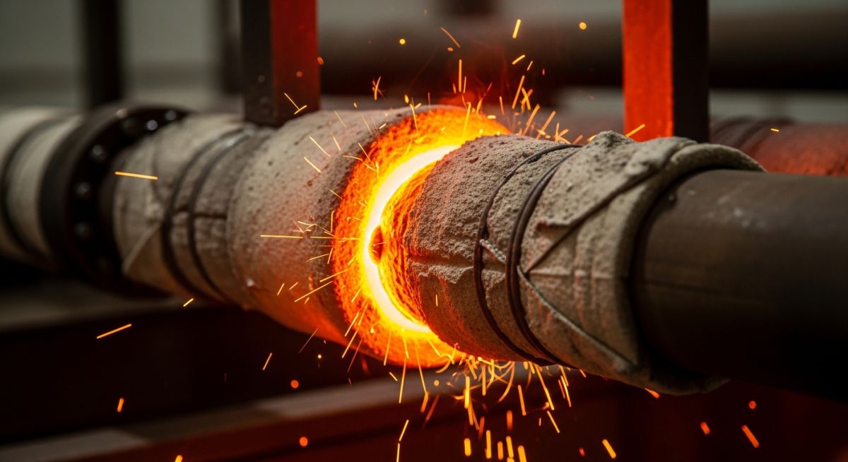
In my 20+ years of managing piping integrity in high-pressure petrochemical plants, I have seen spectacular failures that could have been completely avoided. One of the most common culprits is the neglect or improper execution of thermal stress relief. When you strike an arc and deposit weld metal, you are not just joining two pieces of steel; you are creating a localized zone of extreme thermal expansion and contraction. As the weld pool cools rapidly, it locks in massive residual tensile stresses that often approach the yield strength of the base material.
Without a precise thermal cycle to relax these stresses, your piping system is a ticking time bomb, highly susceptible to hydrogen-induced cracking, stress corrosion cracking, and sudden brittle fracture. This guide breaks down the exact engineering principles, code requirements, and field procedures needed to execute this critical process safely.
- Understand how thermal stress relief prevents catastrophic brittle fracture in heavy-wall piping.
- Master the heating and cooling rate calculations mandated by ASME B31.3 and ASME Section VIII.
- Learn to identify service conditions, such as amine or caustic service, where thermal treatment is mandatory regardless of wall thickness.
- Implement robust field verification protocols to guarantee quality control and hardness compliance.
Complete Course on
Piping Engineering
Check Now
Key Features
- 125+ Hours Content
- 500+ Recorded Lectures
- 20+ Years Exp.
- Lifetime Access
Coverage
- Codes & Standards
- Layouts & Design
- Material Eng.
- Stress Analysis
Understanding Post Weld Heat Treatment Code Requirements
To understand why we perform thermal stress relief, we must look at the microstructural level. During welding, the Heat Affected Zone (HAZ) undergoes rapid thermal cycling. In carbon and low-alloy steels, this rapid cooling often leads to the formation of martensite—a highly stressed, hard, and brittle phase. By heating the weldment to a temperature below the lower transformation range (typically 590°C to 720°C depending on the material), we allow several critical metallurgical phenomena to occur.
First, the yield strength of the material drops significantly at elevated temperatures. The locked-in elastic residual stresses exceed this temporary lower yield strength, causing localized plastic deformation (creep) which relaxes the stress. Second, carbon atoms diffuse out of the highly strained martensitic lattice, transforming it into a ductile tempered martensite structure. Third, hydrogen atoms trapped in the weld metal during welding are highly mobile at elevated temperatures and diffuse out of the steel, eliminating the risk of hydrogen-induced cracking (HIC).
In my field audits, I frequently catch technicians attempting to speed up the cycle by increasing the heating rate or cutting the soak time short. Under-heating fails to reduce the residual stresses to safe levels and leaves the HAZ brittle. Conversely, over-heating can push the material past its lower critical transformation temperature (Ac1), causing recrystallization that permanently degrades the tensile and yield strength of the base metal. Always verify thermocouple calibration before starting.
Calculating Heating and Cooling Rates
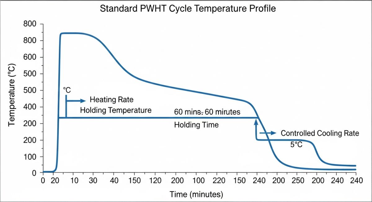
The rate at which a weldment is heated and cooled is strictly regulated to prevent thermal gradients that could introduce new residual stresses. According to ASME Section VIII Division 1, the heating and cooling rates above 427°C (800°F) must be calculated based on the maximum material thickness.
The standard formula for the maximum heating rate (HR) in degrees Celsius per hour is:
Where T is the nominal wall thickness in millimeters. However, the code specifies that the heating rate must never exceed 222°C/hr (400°F/hr) and does not need to be less than 56°C/hr (100°F/hr).
Similarly, the maximum cooling rate (CR) in degrees Celsius per hour is calculated as:
Where T is the nominal wall thickness in millimeters. The cooling rate must never exceed 278°C/hr (500°F/hr) and does not need to be less than 56°C/hr (100°F/hr). Below 427°C (800°F), the assembly can be cooled in still air.
Standard Holding Temperatures and Soak Times
The table below outlines the standard holding temperatures and minimum soak times for common piping materials under ASME B31.3. Note that these values apply to standard carbon and low-alloy steels. Special service conditions may require higher temperatures or longer holding times.
| ASME P-Number | Base Material Type | Holding Temp Range (°C) | Holding Temp Range (°F) | Min. Holding Time (hr/inch) | Min. Time (Minutes) |
|---|---|---|---|---|---|
| P-No. 1 | Carbon Steel | 593 – 649 | 1100 – 1200 | 1.0 | 60 |
| P-No. 3 | Alloy Steel (C-0.5Mo) | 593 – 649 | 1100 – 1200 | 1.0 | 60 |
| P-No. 4 | Alloy Steel (1.25Cr-0.5Mo) | 704 – 746 | 1300 – 1375 | 1.0 | 60 |
| P-No. 5A | Alloy Steel (2.25Cr-1Mo) | 704 – 760 | 1300 – 1400 | 1.0 | 120 |
| P-No. 6 | Martensitic Stainless Steel | 732 – 788 | 1350 – 1450 | 1.0 | 120 |
This matrix maps the core technical entities, structural acronyms, and physical parameters associated with thermal stress relief to their respective industry standards.
| Entity / Acronym | Full Technical Name | Primary Physical Parameter | Governing Standard Reference |
|---|---|---|---|
| HAZ | Heat Affected Zone | Hardness (Max 200-248 BHN) | NACE MR0175 / ISO 15156 |
| HIC | Hydrogen Induced Cracking | Diffusible Hydrogen Content | API RP 941 |
| SCC | Stress Corrosion Cracking | Residual Tensile Stress (MPa) | API 579-1 / ASME FFS-1 |
| Ac1 | Lower Transformation Temp | Phase Change Threshold (°C) | ASME Section II Part D |
Essential Steps for Field PWHT Verification
In my experience, the success of a thermal stress relief operation depends entirely on the diligence of the field inspector. Relying solely on the automated printout from the heating machine is a recipe for failure. You must physically verify the setup at the job site.
-
Thermocouple Attachment: Verify that thermocouples are capacitor-discharge welded directly to the pipe surface. Wrapping them with wire or clamping them is strictly prohibited.
-
Insulation Overlap: Ensure the thermal insulation extends at least 50 mm (2 inches) beyond the edge of the heating band to prevent sharp thermal gradients.
-
Heated Band Width: Confirm that the heated band width is at least three times the wall thickness or 75 mm (3 inches) on either side of the weld centerline, whichever is greater.
-
Calibration Records: Check the calibration certificates of the temperature recorder and the thermocouples. They must be calibrated within the last 12 months.
-
Post-Treatment Hardness Testing: Perform Brinell or Vickers hardness testing on the weld and HAZ. For carbon steel in sour service, the hardness must not exceed 200 BHN.
Executing the Post Weld Heat Treatment Procedure Safely
Field Case Study: Real-World Application
During a routine turnaround at a major refinery, wet fluorescent magnetic particle testing (WFMPT) revealed extensive cracking in the heat-affected zone of a 10-inch Schedule 80 carbon steel line carrying rich amine. The piping had been modified during a previous shutdown. The field team had skipped thermal stress relief because the wall thickness was only 15 mm, which is below the standard 19 mm threshold where ASME B31.3 mandates treatment. They failed to realize that amine service is highly corrosive and induces alkaline stress corrosion cracking (ASCC) in highly stressed welds, making thermal treatment mandatory regardless of thickness.
I was called in to design the remediation plan. We cut out the cracked spool and welded in a new section using a low-hydrogen SMAW process. We then implemented a localized electrical resistance heating cycle. The weld was heated to 620°C (1150°F) at a controlled rate of 150°C/hr, held for 2 hours, and cooled at 180°C/hr. Post-treatment hardness testing showed a maximum of 185 BHN across the HAZ. Subsequent inspections over the next five years showed zero cracking, proving that proper thermal stress relief is non-negotiable in corrosive environments.
This case highlights a critical lesson: code thickness exemptions are only valid for benign services. When dealing with corrosive process fluids like amine, caustic, or wet sour gas, you must always refer to service-specific standards like API RP 945 or NACE MR0175, which override standard code thickness exemptions.
Frequently Asked Engineering Questions
What is the primary difference between stress relieving and PWHT?
When is PWHT mandatory under ASME B31.3?
How does wall thickness affect the heating and cooling rates?
What are the consequences of over-heating during PWHT?
Can localized PWHT be performed instead of full furnace heating?
How is the success of a PWHT cycle verified on-site?
===

📚 Recommended Resources: Post Weld Heat Treatment
Read these Guides
🎓 Advanced Training


Related posts:
![A mechanical sucker rod pumpjack operating in an oil field at sunset]()
What is Sucker Rod Pump System in Oil Production?
![Piping material engineer reviewing technical specifications on a tablet in an industrial plant.]()
How a Piping Material Engineer Drives Industrial Project Success
![Industrial refinery plant showing various types of static equipment]()
What is Static Equipment? Types and List of Static Equipments
![Side-by-side comparison of industrial process piping and power plant steam piping systems.]()
Differences Between ASME B31.3 and B31.1: B31.3 vs B31.1
![Large industrial steel storage tank under construction with cranes and scaffolding]()
Storage Tank Construction Method Statement: Step-by-Step Engineering Guide
![Cutaway diagram of a globe control valve highlighting the internal valve trim components]()
What is a Valve Trim? Types, Components, and Selection


