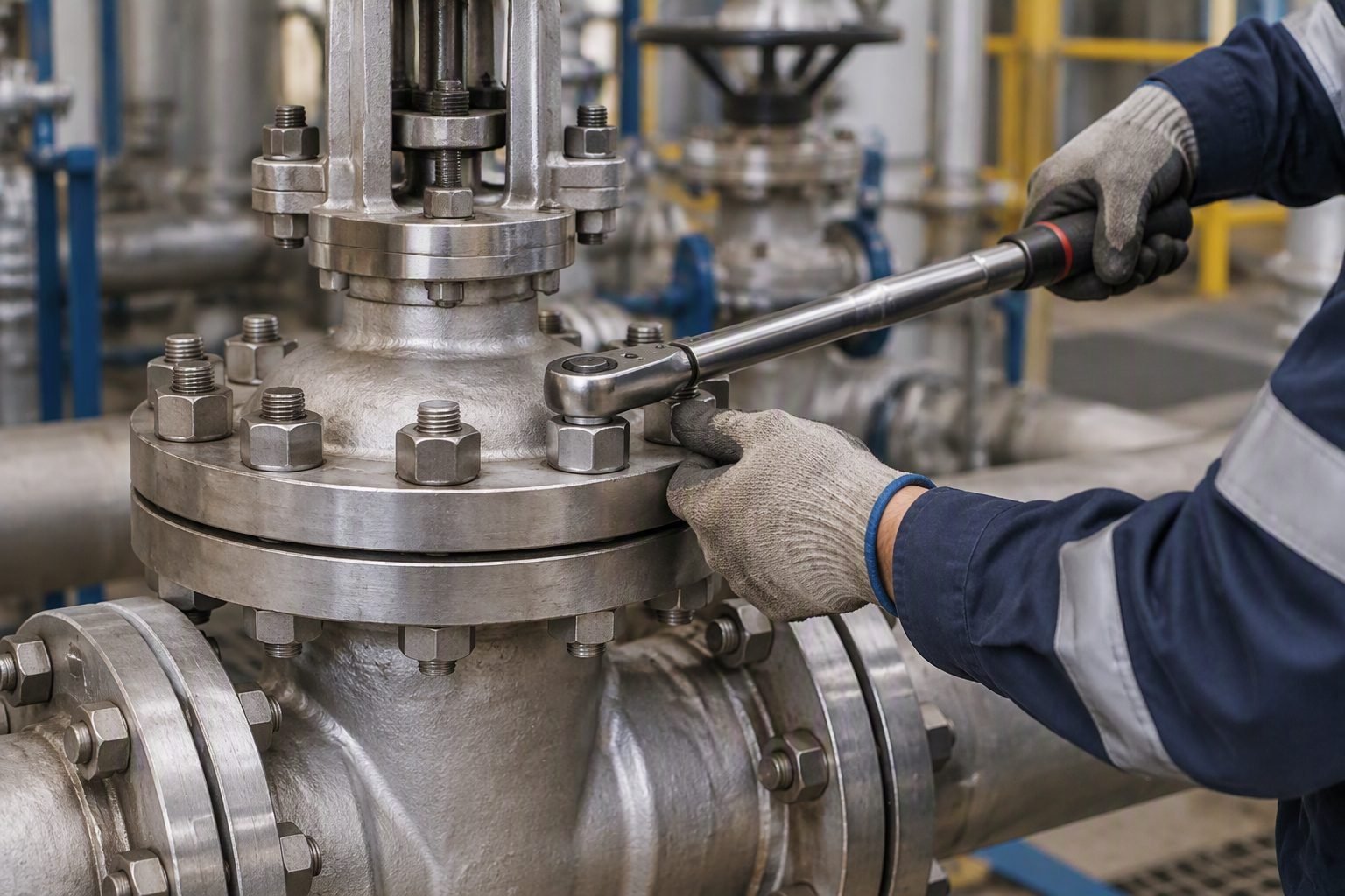
Pneumatic Valve Actuator Inspection: Verifying Diaphragm Rupture
During my twenty years commissioning continuous process facilities, I have investigated countless control loop failures where technicians prematurely condemned a spring-return control valve assembly based solely on erratic positioning. When an industrial pneumatic valve actuator exhibits sluggish stroke response or continuous supply air venting from the casing breather port, field personnel frequently assume an internal rubber diaphragm membrane rupture has occurred.
However, blindly unbolting the diaphragm casing without a methodical pre-verification sequence often masks the root failure mechanism—such as pilot regulator hunting, spring seat binding, or O-ring extrusion in the positioner relay. In this guide, I will walk you through the exact diagnostic framework required to inspect your pneumatic valve actuator safely and accurately in compliance with international engineering codes.
Key Engineering Takeaways
- Differentiate between pilot pneumatic venting and true elastomeric membrane tears using differential pressure logging.
- Calculate safe spring preload relaxation limits per ASME BPVC Section VIII guidelines prior to casing disassembly.
- Apply systematic isolation procedures to prevent catastrophic spring energy release during maintenance.
Pneumatic Valve Actuator Diagnostic Engineering and Failure Modes
When troubleshooting a suspected pneumatic valve actuator diaphragm failure, you must first understand the fundamental force balance governing spring-return diaphragm assemblies. The net downward thrust (F_net) generated by the actuator is governed by the effective diaphragm area (A_e), the applied control signal pressure (P_s), and the opposing spring force (F_spring), expressed through the primary equilibrium equation:
Where k_s represents the combined spring rate of the internal compression springs and x is the stem travel displacement. If the rubber membrane develops a pinhole tear, supply air bypasses from the top casing chamber directly into the spring chamber, equalizing differential pressure across the diaphragm and causing the valve to drift toward its fail-safe position.
Elastomeric Degradation and Thermal Limitations
The elastomeric membrane within a high-performance pneumatic valve actuator typically consists of fabric-reinforced Nitrile (NBR), Viton (FKM), or Ethylene Propylene Diene Monomer (EPDM). Selecting the correct compound requires strict adherence to temperature and chemical compatibility tables outlined in ASTM D2000.
In my plant site audits, I frequently observe premature embrittlement caused by compressed air supply containing excessive compressor lubricant carryover or moisture. Synthetic diester-based lubricants attack standard NBR elastomers rapidly, causing swelling, loss of tensile strength, and eventual tearing along the bolt circle clamping bead.
CRITICAL SAFETY WARNING: Stored Spring Energy
Spring-return pneumatic valve actuators store immense mechanical energy in their compression springs. Never loosen or remove casing perimeter bolting without first installing approved all-thread jacking bolts of adequate tensile strength (minimum ASTM A193 Grade B7) or fully relieving actuator bench set pressure per ISA 75.13.01 protocol.
Pre-Disassembly Diagnostic Verification Protocol
Before reaching for hand tools to tear down your pneumatic valve actuator, execute this four-step validation sequence to confirm diaphragm integrity without unnecessary downtime:
- Supply Line Isolation: Close the instrument air isolation valve and bleed the pneumatic controller output line to verify if venting stops instantly.
- Breather Port Leak Test: Apply a soap bubble solution around the spring chamber vent port while maintaining steady-state mid-stroke position. Continuous bubbling confirms internal leakage.
- Positioner Feedback Check: Verify that valve stem position matches the 4-20mA control signal; a static offset paired with high air consumption indicates internal bypass.
- Bench Set Pressure Verification: Isolate the actuator completely and apply a calibrated pneumatic test bench pressure source to record actual stroke versus input pressure curves.
By following these rigorous diagnostic steps, maintenance engineers can isolate true diaphragm failures from positioner pneumatic relay failures, saving precious turnaround hours and preventing unnecessary hardware replacement.
Advantages
- Provides high frequency response and exceptional positioning resolution for modulating control loops.
- Features frictionless rolling diaphragm designs that eliminate stem hysteresis in small-to-medium strokes.
- Offers inherently fail-safe spring-return action complying with emergency shutdown (IEC 61508) requirements.
- Simpler internal construction than piston actuators, allowing faster seal replacements in the field.
- Lower initial capital cost compared to heavy-duty double-acting pneumatic piston configurations.
Disadvantages
- Elastomeric membranes have limited operating temperature ranges compared to metallic bellows or pistons.
- Vulnerable to chemical attack and embrittlement from contaminated or oil-laden instrument air supplies.
- Output thrust decreases near full stroke extension as compression spring opposing force increases.
- Casing bolting requires careful torque sequencing to prevent uneven clamping stress and premature tearing.
- Bulkier physical footprint compared to compact rack-and-pinion pneumatic actuators of equivalent torque output.
Refinery Crude Distillation Units
In high-temperature crude preheat trains, control valves rely on robust pneumatic valve actuator assemblies with fluoroelastomer membranes. Routine diagnostic verification ensures emergency shutdown bypass lines remain operable without premature spring relaxation during thermal cycling.
Petrochemical Polymerization Reactors
Reactor feed injection skids utilize precise spring-return actuators governed by API 6D and ISA standards. Quick membrane inspection protocols prevent catastrophic reactor runaway scenarios by guaranteeing fail-safe closure upon air header pressure drops.
Cryogenic Liquefied Natural Gas Facilities
LNG liquefaction trains operate control valves at extreme sub-zero temperatures. Specialized low-temperature pneumatic valve actuator diaphragms require specialized non-destructive testing and acoustic emission monitoring to detect micro-cracks before complete structural failure occurs.
Pharmaceutical Clean Steam Sterilization
Clean utility systems demand sanitary diaphragm actuators complying with ASME BPE standards. Verifying diaphragm integrity without violating aseptic boundaries ensures zero microbial contamination during automated clean-in-place cycles.
Offshore Production Platforms
Subsea and topside production manifolds incorporate corrosion-resistant pneumatic valve actuator units subjected to high vibration and salt spray. Periodic bench testing guarantees that diaphragm flexibility and spring preload retain full compliance under severe environmental loading.
Proper maintenance and inspection of control valve hardware require strict adherence to material limits and sizing parameters. When evaluating an industrial pneumatic valve actuator, instrumentation engineers must correlate spring ranges, operating pressure envelopes, and elastomer degradation limits against established industrial guidelines. The dataset below outlines the essential engineering thresholds required to determine whether an installed elastomer membrane remains fit for service or requires immediate replacement.
Every maintenance schedule must reference these baseline operational metrics during turnaround inspections. Exceeding maximum supply pressure ratings or operating outside recommended temperature windows severely compromises diaphragm integrity, leading to premature fatigue and unplanned process shutdowns.
| Parameter Category | Standard Operating Limit | Critical Failure Threshold | Governing Code / Standard |
|---|---|---|---|
| Supply Air Pressure | 1.4 bar to 4.1 bar (20-60 psi) | > 6.0 bar (87 psi) continuous | ASME B16.34 / API 553 |
| Elastomer Temperature | -29 degrees C to +82 degrees C | < -40 degrees C or > 120 degrees C | ASTM D2000 / ISO 3601 |
| Spring Return Force | 100% to 110% bench set rating | > 15% relaxation loss | ISA-75.25.01 |
| Diaphragm Thickness | 2.5 mm to 4.5 mm nominal | > 20% localized thinning | API 6D / ASME Sec VIII |
Note: All maximum allowable working pressure ratings must be verified against manufacturer nameplate data before executing any localized pneumatic isolation or bench calibration sequence.
Understanding the intricate network of mechanical sub-assemblies inside a pneumatic control valve requires a structured ontological breakdown. The architecture of spring-return and double-acting units involves specialized components interacting under high dynamic stress. The matrix below maps critical entity relationships, governing design standards, and physical metrics essential for root-cause analysis.
Systems engineering teams utilize this relational mapping to standardize diagnostic nomenclature across global asset fleets, minimizing miscommunications during urgent corrective interventions.
| Entity / Component | Structural Acronym | Primary Physical Parameter | Applicable Standard Ref |
|---|---|---|---|
| Pneumatic Actuator Assembly | PAA | Thrust force and stroke length | ASME B31.3 / ISO 9001 |
| Elastomeric Membrane | EMB | Tensile strength and durometer | ASTM D412 / ISO 37 |
| Compression Spring Pack | CSP | Spring rate and preload compression | ASTM A125 / EN 10270 |
| Positioner Instrumentation | EPP | Signal linearity and air consumption | NAMUR / IEC 60534 |
Cross-reference: Entity relationships must align with plant-wide safety instrumented system (SIS) validation records to maintain compliance.
Field verification of a suspected diaphragm failure requires a methodical, step-by-step approach to prevent accidental pressure release and equipment damage. Before opening any pneumatic casing, instrumentation technicians must execute rigorous isolation protocols aligned with OSHA Lockout Tagout and internal plant safety directives. The checklist below outlines mandatory checkpoints required before assuming internal elastomer degradation has occurred.
Skipping any verification phase can result in misdiagnosis, where external air leakage or positioner calibration drift is incorrectly blamed on an intact internal membrane.
Field Inspection Protocol Checklist
- 1. Isolate instrument air supply and depressurize the pneumatic actuator casing completely in accordance with ASME BPVC Section VIII guidelines.
- 2. Inspect the actuator vent port for continuous air leakage or oily condensate discharge indicating seal failure.
- 3. Verify valve stroke responsiveness and check for hysteresis anomalies against baseline bench calibration sheets.
- 4. Loosen casing fasteners in a strict criss-cross torque pattern to safely relieve internal compression spring tension.
- 5. Inspect the rubber diaphragm membrane for cracking, hardening, blistering, or chemical attack degradation.
- 6. Examine compression springs for corrosion pitting, fracture lines, or loss of free-length dimension.
- 7. Clean all internal sealing surfaces and replace O-rings and backup rings prior to reassembly.
- 8. Perform a hydrostatic or pneumatic leak test of the assembled casing per ASME B31.3 testing requirements.
Upon completing every item on this checklist, sign off the maintenance work order and update the Computerized Maintenance Management System (CMMS) with exact replacement part batch numbers for full traceability.
Field Case Study: Real-World Application
A severe operational upset occurred at a coastal petrochemical refinery when a critical emergency shutdown control valve failed to close on demand, threatening overpressurization of a fractionation unit. Initial plant reports assumed an internal diaphragm rupture had disabled the spring-return actuator mechanism. An emergency engineering investigation was immediately dispatched to inspect the internal hardware.
Field Case Problem: Misdiagnosed Actuator Failure
Plant technicians assumed an immediate elastomer rupture without checking peripheral control loops, leading to unnecessary downtime.
- Continuous air bleed escaping from the positioner exhaust port mistaken for diaphragm failure.
- Lack of differential pressure instrumentation across the actuator loading chambers.
- Corroded instrument air supply filter regulator introducing moisture into the pilot signal line.
- Premature disassembly attempted without following proper spring tension release protocols.
Our specialist engineering team intervened, establishing safe isolation barriers and executing a systematic diagnostic review in accordance with API 553 refinery instrument standards. Disassembly revealed that the rubber diaphragm was entirely intact and undamaged, but the internal compression springs were fouled with heavy salt corrosion and water ingress from a neglected air header drain.
Field Case Outcome: Precise Root-Cause Resolution
Systematic inspection corrected the diagnostic error, restoring unit integrity and preventing recurring instrument failures.
- Identified and replaced heavily corroded compression springs rather than discarding the functional diaphragm.
- Installed an upgraded coalescing air filter regulator to eliminate moisture contamination.
- Updated plant standard operating procedures to mandate differential pressure testing prior to actuator teardown.
- Achieved full compliance with ASME B31.3 valve testing protocols, saving thousands in unnecessary parts replacement.
Recommendation: Instrumentation engineers must never assume diaphragm rupture solely based on sluggish valve travel or vent port noise. Always execute a complete pneumatic isolation, supply pressure check, and systematic internal inspection to guarantee accurate maintenance execution.
Frequently Asked Engineering Questions
What are the primary indicators of a ruptured pneumatic valve actuator diaphragm?
- Continuous bleeding of supply air through the spring-case atmospheric vent port during static positioning.
- Unexplained actuator sluggishness or complete loss of stroking force under high differential pressure loads.
- Erratic process variable control oscillation directly traceable to unstable upper chamber pressure retention.
How does ASME ASME B31.3 govern actuator pressure testing?
- Never exceed the maximum allowable working pressure stamped on the actuator nameplate during bench testing.
- Isolate the positioner and instrument accessories to prevent delicate feedback linkages from sustaining overpressure damage.
- Perform hydrostatic or pneumatic shell tests strictly in accordance with API 598 valve inspection criteria when required.
What causes premature elastomer degradation in spring-return units?
- Exposure to unconditioned supply air containing compressor oil hydrocarbons that dissolve nitrile rubber membranes.
- Thermal aging exceeding the maximum continuous operating temperature rating of the specific elastomer compound.
- High-frequency micro-oscillations that induce localized flex fatigue around the piston stem clamping plate.
How should technicians safely decompress heavy compression springs?
- Utilize a threaded all-rod press tool or approved safety cage to evenly unload internal spring tension.
- Gradually loosen housing bolts in a crisscross pattern, backing off opposing fasteners symmetrically.
- Never rely on improvised clamping fixtures or pneumatic pressure to counteract high-rate compression springs.
What documentation is required after replacing an actuator diaphragm?
- Update the Computerized Maintenance Management System with exact replacement part lot numbers and elastomer compound specs.
- Log pre- and post-maintenance stroke time test results to ensure compliance with critical safety loop response times.
- File calibration certificates for associated positioners and pressure regulators in the plant historical data repository.
Field Recommendation
Based on my two decades of hands-on commissioning and troubleshooting experience across major processing facilities, I advise instrumentation teams to adopt a rigorous, proactive stance when dealing with pneumatic valve actuator health. Never assume a casing vent leak is an immediate catastrophic diaphragm failure without first verifying supply regulator stability and checking for accumulated condensation.
- If your facility operates in highly corrosive offshore or chemical environments, specify fluoroelastomer or fabric-reinforced EPDM diaphragms during initial procurement to extend mean time between failures by at least threefold.
- When conducting routine preventive maintenance, always replace the center stem O-rings and backup rings whenever you open the casing, as disturbing the clamping plate often compromises aged secondary seals.
- If a critical control valve exhibits sluggish dead band behavior, mandate a bench stroke test with a calibrated pressure source rather than immediately adjusting positioner gain parameters to mask underlying mechanical friction.
- Always verify that instrument air supply dew points are maintained at least ten degrees Fahrenheit below the minimum local ambient temperature to prevent internal icing and premature elastomer embrittlement.
Complete Course on
Piping Engineering
Check Now
Key Features
- 125+ Hours Content
- 500+ Recorded Lectures
- 20+ Years Exp.
- Lifetime Access
Coverage
- Codes & Standards
- Layouts & Design
- Material Eng.
- Stress Analysis
