Mastering Pipe Routing Concepts: A Professional Engineering Guide
Key Takeaways
- Understanding the critical role of Pipe Routing Concepts in ensuring system NPSH and thermal flexibility.
- Strategies for optimizing pipe rack space to reduce material costs and structural loading.
- Application of ASME B31.3 standards to layout design for long-term operational safety.
What are Pipe Routing Concepts?
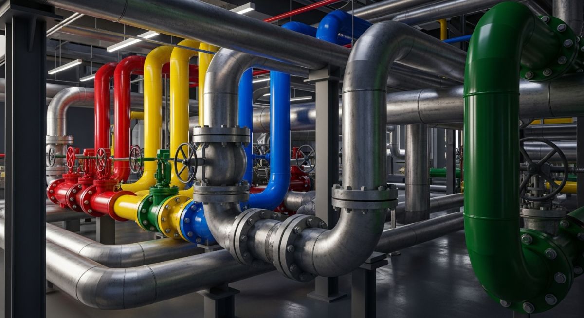
Pipe Routing Concepts refer to the systematic approach of arranging piping systems within an industrial plant. It involves balancing hydraulic requirements, ASME compliance, maintenance accessibility, and structural constraints. Effective routing ensures minimal pressure drops, accommodates thermal expansion, and provides safe operator access to valves and instruments while minimizing overall project costs.
“In my 20 years of field inspections, I’ve seen that 90% of operational headaches stem from poor initial routing. If a technician cannot reach a valve comfortably, they won’t maintain it. Always route for the human who has to live with your design for the next 30 years.”
– Atul Singla, Founder of EPCLand
Complete Course on
Piping Engineering
Check Now
Key Features
- 125+ Hours Content
- 500+ Recorded Lectures
- 20+ Years Exp.
- Lifetime Access
Coverage
- Codes & Standards
- Layouts & Design
- Material Eng.
- Stress Analysis
Knowledge Check: Pipe Routing Concepts
Test your engineering layout expertise (Question 1 of 5)
Core Skills Required for Designing Efficient Pipe Routing Concepts
Designing industrial piping is a multi-disciplinary effort that requires more than just proficiency in 3D modeling software. A piping engineer must possess a deep understanding of spatial visualization to predict clashes before they occur in the virtual environment. Mastery of Pipe Routing Concepts starts with the ability to interpret a P&ID (Piping and Instrumentation Diagram) and translate its logical connections into a physical, three-dimensional reality that respects gravity, fluid dynamics, and structural integrity.
Beyond technical drafting, a core skill involves stress awareness. Engineers must be able to identify “stiff” systems that lack thermal flexibility, potentially leading to nozzle failures at expensive equipment like pumps or turbines. Knowledge of metallurgy and support selection is also non-negotiable. For those looking to deepen their foundational knowledge, the Official ASME Codes and Standards provide the legal and safety framework within which all Pipe Routing Concepts must operate.
Fundamental Pipe Routing Concepts Every Engineer Must Know
The primary objective of any piping layout is the orderly arrangement of lines. One of the most critical Pipe Routing Concepts is the use of common “Pipe Racks.” Pipe racks act as the arterial highway of a plant, carrying utilities and process fluids between units. Engineers must organize these racks by placing larger, heavier, and hotter pipes on the outer edges or lower tiers to simplify structural loading and heat dissipation.
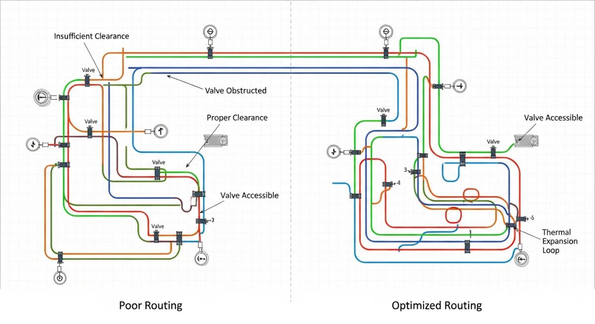
Another fundamental pillar is Accessibility and Maintainability. It is a golden rule in Pipe Routing Concepts that any valve requiring frequent operation must be located within “operator reach” (typically between 600mm and 1500mm from the grade or platform). If a valve must be placed higher, permanent ladders or chain-wheels must be integrated into the design. Furthermore, clearance for “tube bundle pulling” in heat exchangers and “motor removal” for pumps must be reserved as “dead space” where no piping can be routed.
Finally, Gravity Flow and Sloping represent a specialized subset of Pipe Routing Concepts. In flare headers or condensate return lines, the pipe must be physically sloped toward a collection vessel to prevent liquid pocketing. Pocketing in a steam system can lead to catastrophic “Water Hammer” events, which can rupture fittings and endanger personnel. Designers must meticulously calculate “Centerline Elevations” (CL) to ensure consistent slopes are maintained across long horizontal runs.
Advanced Pipe Routing Concepts for High-Pressure Systems
When dealing with high-pressure and high-temperature (HPHT) environments, Pipe Routing Concepts must evolve from simple spatial arrangement to complex Flexibility Analysis. In these systems, the piping behaves more like a living organism that expands and contracts significantly. Advanced routing utilizes Expansion Loops and 3D offsets to absorb this movement without transferring excessive force to sensitive equipment nozzles. According to API Standards, even a few millimeters of unintended movement can cause mechanical seal failure in rotating equipment.
Engineers must also implement Hydraulic Optimization within their Pipe Routing Concepts. For high-velocity gas lines, the use of long-radius elbows and specific branch connections (like 45-degree laterals) is essential to minimize turbulence and erosion-corrosion. This level of detail ensures that the piping system remains operational for its intended 25-30 year lifecycle without unplanned thickness gauging or emergency patches.
Industry Standards Governing Modern Pipe Routing Concepts (ASME/API)
Compliance isn’t optional; it is the backbone of safety. ASME B31.3 governs the majority of process piping, dictating wall thickness, reinforcement requirements, and the logic behind Pipe Routing Concepts. For instance, the standard provides specific guidance on the minimum distance between welds and the use of “Miter Bends” versus standard fittings.
| Concept Parameter | Standard Requirement | Engineering Impact |
|---|---|---|
| Thermal Expansion | ASME B31.3 Appendix C | Prevents nozzle overloading and fatigue failure. |
| Pump Suction Run | API RP 686 | Minimizes turbulence to prevent pump cavitation. |
| Support Spacing | MSS SP-58 | Ensures pipe deflection stays within allowable limits. |
| Valve Accessibility | OSHA 1910.37 | Guarantees safe egress and operator reachability. |
Common Pitfalls in Implementing Complex Pipe Routing Concepts
The most frequent error in modern 3D design is “Clash Ignorance”—relying too heavily on software to flag interferences without understanding the physical reality of Pipe Insulation. Designers often route pipes based on the outside diameter (OD) but forget that 100mm of calcium silicate insulation will create a physical clash in the field.
Additionally, failing to account for Hydrostatic Test Loads is a dangerous oversight. A pipe designed to carry light gas may be perfectly supported for its operating life, but if the Pipe Routing Concepts do not account for the weight of water during a hydro-test, the entire system could sag or collapse the primary supports.
Thermal Expansion Estimator for Pipe Routing
Calculate the required expansion offset to validate your Pipe Routing Concepts.
Engineering Tip: If total expansion exceeds 50mm, your Pipe Routing Concepts should include an expansion loop or an “L-Bend” to prevent excessive stress on equipment nozzles according to ASME B31.3.
EPCLand YouTube Channel
2,500+ Videos • Daily Updates
Case Study: Brownfield Debottlenecking through Pipe Routing Concepts
Location: Major Gulf Coast Refinery Expansion (2026)
The Challenge
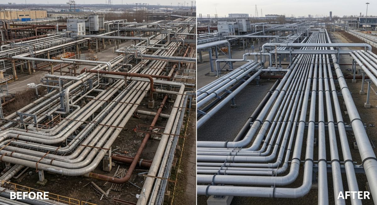
A Tier-1 refinery required a 25% capacity increase in its Crude Distillation Unit (CDU). The primary obstacle was a “spaghetti” of existing 1970s-era piping that lacked modern 3D documentation. Initial Pipe Routing Concepts proposed by a third party resulted in over 450 physical clashes with primary structural steel and existing cable trays.
The Engineering Solution
Our team utilized 3D Laser Scanning to create a “Point Cloud” of the existing facility. By applying advanced Pipe Routing Concepts, we redesigned the main header to utilize “Tiered Racks,” placing the high-temperature steam lines on a dedicated upper level. This move created the necessary 2.1-meter head clearance for operator access while providing the required ASME B31.3 thermal flexibility through a series of vertical expansion loops.
Project Results:
- Zero Field Clashes: 3D-integrated routing eliminated rework costs.
- 15% Material Savings: Optimized pathing reduced the total number of elbows and fittings.
- Safety Compliance: Fully met OSHA 1910.37 requirements for egress.
“The key was not finding more space, but using the existing space more intelligently through logical Pipe Routing Concepts.”
— Lead Piping Engineer, EPC Project Team
Expert Insights: Lessons from 20 years in the field
Avoid “Dead-Legs” at all costs: In Pipe Routing Concepts, creating a stagnant section of pipe (dead-leg) is a recipe for internal corrosion and microbiological growth. Always ensure the routing promotes continuous flow or includes proper high-point vents and low-point drains.
Respect the “Cold Spring” Myth: While some Pipe Routing Concepts suggest using “Cold Spring” (pulling pipe into place) to reduce nozzle loads, it is notoriously difficult to execute accurately in the field. Rely on proper loop design and thermal flexibility instead.
Symmetry is not always Efficiency: Engineers often strive for symmetrical layouts for aesthetic reasons. However, effective Pipe Routing Concepts prioritize the shortest path for high-pressure drops and the most accessible path for manual control valves.
Frequently Asked Questions: Pipe Routing Concepts
What are the most critical factors in Pipe Routing Concepts?
How do you handle thermal expansion in congested pipe racks?
Why is a minimum slope required for flare and steam headers?
What is the “Golden Triangle” of Pipe Routing?
How does P&ID data influence Pipe Routing Concepts?
Is 3D laser scanning mandatory for brownfield routing?

Related posts:
![High-grade industrial Wing Nut Types and Applications for mechanical assemblies.]()
Wing Nut Types and Applications: The 2026 Engineering Guide
![Industrial Monorail Crane Systems installed in a modern manufacturing plant 2026.]()
Monorail Crane Systems: Design, Types & 2026 Standards Guide
![Lead engineer performing a Factory Acceptance Test FAT on an industrial skid system 2026]()
Factory Acceptance Test FAT: The 2026 Engineering Guide to Zero-Defect Delivery
![Professional engineering workspace showing a Basis of Design document layout for a 2026 project.]()
Basis of Design: How to Write a BOD for Engineering Projects in 2026
![Industrial Flare Knockout Drum Sizing and installation in a refinery relief system.]()
Flare Knockout Drum Sizing: Design & API 521 Standards (2026 Guide)
![Advanced Reboiler Control Systems in a modern petrochemical refinery 2026.]()
Reboiler Control Systems: Engineering Guide to Precision Control 2026


