Calculating Pipe Rack Wind Load for Structural Integrity
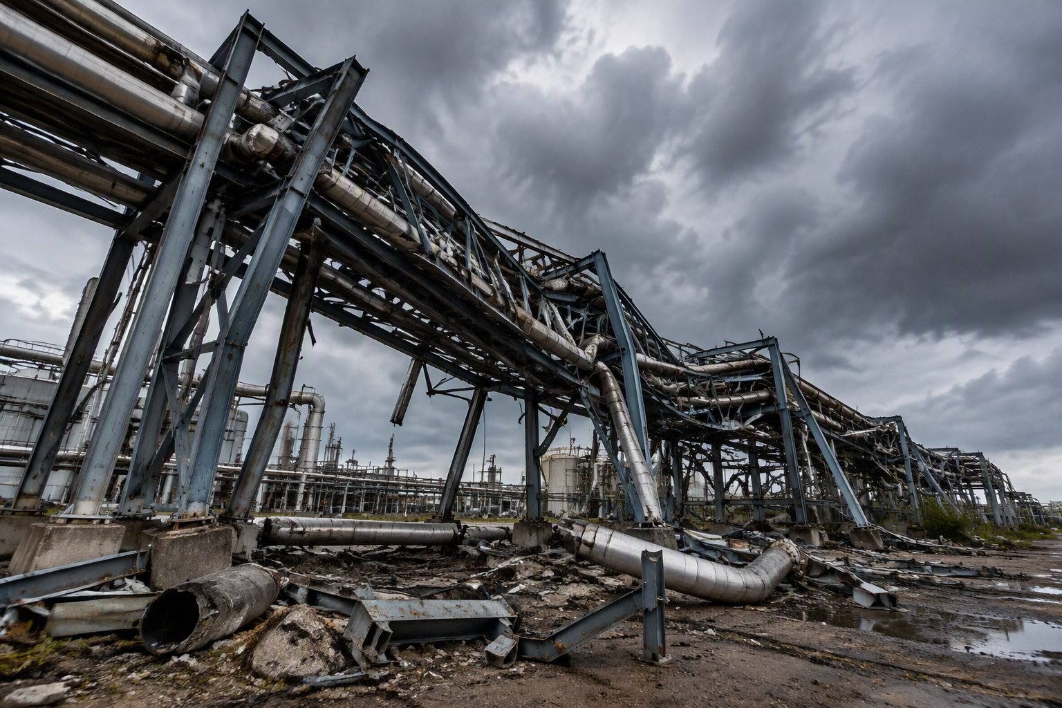
Walking through a plant yard after a severe meteorological event to inspect a twisted, fallen pipe rack is an experience that changes an engineer’s perspective forever. In my two decades designing heavy industrial facilities, I have investigated multiple structural failures where underestimating wind forces turned multi-tier pipe racks into heaps of bent steel and ruptured lines. A tall industrial pipe rack structure lies bent and collapsed after a severe storm, with fallen pipe supports and debris scattered on the ground, illustrating the structural consequence of underestimated wind load on pipe rack design.
Accurate wind load calculation is not merely a checkbox exercise for structural permit submittals; it is the fundamental defense protecting hazardous chemical transport lines from shear failure. When gusts strike bundled piping tiers, the projected surface area multiplies rapidly, creating massive overturning moments on the support bents.
Key Engineering Takeaways
- Apply ASCE 7-16 Chapter 29 provisions for open-ended structures and stacked pipe bundles.
- Account for shielding factors and solidity ratios when calculating force coefficients for multi-tier piping arrangements.
- Integrate rigorous lateral deflection limits to protect sensitive flanged connections from excessive bending moments.
ASCE 7-16 Methodologies for Pipe Rack Wind Load Engineering
Calculating accurate wind loads on industrial pipe racks requires moving beyond standard building envelopes into specialized structural frameworks. Pipe racks are classified under ASCE 7-16 Chapter 29 as “Other Structures,” meaning they lack continuous walls and experience complex aerodynamic interactions across multiple tiers of cylindrical pipes.
The foundational design velocity pressure equation is defined as qz = 0.00256 * Kz * Kzt * Kd * Ke * V^2, where V represents the ultimate design wind speed. In my project workflows, I establish the velocity pressure exposure coefficient (Kz) based on the specific surface roughness category of the terrain surrounding the petrochemical facility.
Evaluating Force Coefficients for Pipe Bundles
Unlike solid walls, pipe racks consist of open frames filled with circular elements. The force coefficient (Cf) depends heavily on the solidity ratio (epsilon), which is the ratio of solid projected area to gross area of the frame. For rounded structural shapes and insulated pipes, ASCE 7-16 provides empirical curves that account for Reynolds number dependencies.
When multiple tiers of piping run parallel, downstream pipes experience aerodynamic shielding from upstream members. I apply a shielding reduction factor calculated from the spacing-to-diameter ratio, ensuring we do not overly penalize lower tiers while maintaining conservative safety margins for upper levels.
Critical Design Warning
Never treat bundled insulated pipes as a single solid rectangular block in wind models. Ignoring individual cylinder drag coefficients leads to severe underestimations of localized bending moments on transverse bent columns during hurricane-force gusts.
Accounting for Insulation and Trays
Process piping frequently carries thermal insulation clad in aluminum or stainless steel jackets, which substantially increases the effective outer diameter. During load calculation, every single line’s outer diameter must include insulation thickness.
Cable trays and instrument racks mounted atop or alongside pipe racks add significant projected area. I enforce a strict audit of all electrical raceways during structural data gathering, as unmapped cable trays often introduce 15% to 25% unexpected lateral wind surface area.
Dynamic Amplification and Gust Effects
Tall pipe racks flexible in the transverse direction are susceptible to along-wind gust dynamic effects. The gust-effect factor (G) for rigid structures defaults to 0.85, but flexible pipe racks require a rigorous dynamic analysis per ASCE 7-16 Section 26.9 to determine natural frequency and damping ratios.
If the fundamental natural frequency falls below 1 Hz, resonant dynamic amplification must be integrated into the base shear calculations to prevent fatigue cracking at column base plates and anchor bolt assemblies.
Engineering Advantages
- Prevents catastrophic structural collapse and catastrophic loss of containment during extreme weather events.
- Optimizes structural steel tonnage by applying accurate solidity ratios rather than over-conservative solid-wall assumptions.
- Ensures full compliance with ASCE 7-16 and OSHA industrial safety mandates.
- Protects delicate flanged connections and welded branch joints from excessive lateral displacement strains.
- Reduces long-term maintenance costs by eliminating micro-cracking in anchor bolt assemblies and base plates.
Engineering Disadvantages
- Demands extensive upfront data collection regarding exact pipe diameters, insulation thickness, and cable tray layouts.
- Increases engineering man-hours required for complex 3D structural modeling and dynamic frequency analysis.
- Can lead to heavier column sections and larger foundation footings, raising initial capital expenditure.
- Requires specialized software capabilities to accurately model shielding factors across multi-tier piping arrangements.
- Adds complexity to brownfield expansion projects where existing pipe rack capacities must be recalculated.
Petroleum Refining Inter-Unit Pipe Racks
Refineries feature sprawling multi-tier pipe racks carrying high-pressure hydrocarbon lines between atmospheric distillation units and hydrotreaters. Rigorous wind load calculations using ASCE 7-16 ensure these primary arteries maintain stability during coastal hurricane landfalls, preventing massive product spills and fire hazards.
Offshore Modular Topsides Support Structures
Modular production topsides incorporate dense pipe racks engineered to withstand extreme maritime gale forces. Accurate dynamic wind profiling is vital because offshore structures experience unshielded, high-velocity wind profiles coupled with floating platform motion.
LNG Liquefaction Facility Cryogenic Piping Racks
Liquefied Natural Gas plants rely on massive pipe racks transporting cryogenic fluids at minus 162 degrees Celsius. Severe wind-induced lateral sway on these racks can stress brittle stainless steel piping and specialized vacuum-jacketed insulation, making accurate ASCE 7-16 wind analysis mandatory for leak prevention.
Chemical Processing Plant Pipe Bridges
Long-span pipe bridges crossing over active plant roadways must resist intense torsional wind loads acting on asymmetrical piping bundles. Structural engineers apply sophisticated force coefficient evaluations to prevent bridge deck twisting and subsequent flange shearing.
Power Generation Steam and Feedwater Racks
Thermal and nuclear power stations utilize heavy pipe racks routing high-temperature steam lines from boiler houses to turbine generators. Calculating thermal expansion alongside extreme wind shear forces ensures support bents accommodate both environmental lateral loads and internal thermal growth.
ASCE 7-16 Wind Load Parameters and Exposure Categories
Accurate calculation of industrial pipe rack wind loads requires precise determination of velocity pressure coefficients, gust effect factors, and force coefficients as mandated by structural design standards. In my structural design practice, underestimating these variables routinely leads to severe structural twisting or catastrophic collapse during extreme meteorological events.
The engineering data table below outlines the core parameters, applicable design standards, and typical numerical ranges utilized when evaluating open-frame industrial pipe racks. Each parameter directly influences the magnitude of the final design wind load transferred into the foundation anchor bolts and structural columns.
| Parameter Description | Standard Reference | Typical Range / Value | Engineering Impact |
|---|---|---|---|
| Basic Wind Speed (V) | ASCE 7-16 Fig. 26.5-1 | 110 to 180 mph | Establishes baseline kinetic energy of wind; squared relationship to design velocity pressure. |
| Exposure Category | ASCE 7-16 Sec. 26.7 | Exposure B, C, or D | Defines surface roughness; Exposure D (coastal) yields significantly higher wind pressures. |
| Gust Effect Factor (G) | ASCE 7-16 Sec. 26.11 | 0.85 (Rigid) to 1.1+ | Accounts for along-wind turbulence; flexible multi-tier pipe racks require dynamic analysis. |
| Force Coefficient (Cf) | ASCE 7-16 Fig. 29.3-1 | 1.2 to 2.0 (Solid/Framed) | Multiplies velocity pressure by projected solid area of structural members and pipe bundles. |
| Importance Factor (Ww) | ASCE 7-16 Table 1.5-2 | 1.0 (Risk Cat II) to 1.25 (Cat III) | Scales wind load based on facility hazard level and post-disaster operational requirements. |
Reviewing these parameters during the preliminary conceptual design phase prevents costly retrofits later. Engineers must verify local meteorological data to avoid underestimating the basic wind speed, especially in hurricane-prone or typhoon-prone regions.
Technical Mapping & Specifications Matrix
Complex industrial plant structures involve the integration of multiple engineering disciplines, governing codes, and software modeling parameters. In my experience leading multidisciplinary piping and structural teams, maintaining a unified data matrix ensures that load paths from pipe shoes down to concrete foundations remain unbroken.
The matrix below maps critical structural entities, standard acronyms, physical calculation variables, and governing code references. This structured breakdown serves as a quick-reference guide for piping stress engineers and structural designers collaborating on heavy industrial rack systems.
| Entity / Component | Acronym / Symbol | Governing Standard | Core Specification & Application |
|---|---|---|---|
| Velocity Pressure | qz | ASCE 7-16 Sec. 27.4 | Calculated at height z using velocity pressure exposure coefficient Kz and topographic factor Kzt. |
| Piping Bundle Area | Af_pipe | ASCE 7-16 / ASME B31.3 | Projected solid area of insulated and uninsulated pipes treated as a continuous solid obstruction. |
| Structural Steel Framing | AISC 360 | AISC 360-16 | Governs member sizing, unbraced length ratios, and combined axial-flexure interaction equations. |
| Anchor Bolt Assembly | ACI 318 | ACI 318-19 | Calculates concrete breakout strength and tensile uplift resistance caused by overturning wind moments. |
| Dynamic Amplification | Vort-Shed | ASCE 7-16 App. H | Evaluates cross-wind galloping and vortex shedding potential for tall, slender structural bents. |
Proper synchronization between piping stress analysis software (such as Caesar II) and structural finite element packages (such as STAAD.Pro or SAP2000) guarantees that frictional forces and wind-induced anchor loads are accurately transferred without overstressing individual pipe shoes.
Site Verification Checklist for Pipe Rack Wind Design
Rigorous field verification during construction and routine plant turnarounds is essential to confirm that as-built pipe rack configurations match engineering wind load assumptions. When I perform site walkdowns on petrochemical facilities, I frequently inspect for unauthorized pipe additions that alter projected surface areas and invalidate original design calculations.
To ensure complete compliance with ASCE 7-16 and ASME B31.3 standards, use the comprehensive site verification checklist below before signing off on structural stability and piping support readiness.
Pre-Commissioning Wind Load & Structural Integrity Checklist
- Wind Speed Verification: Confirm that the design basic wind speed (V) matches local meteorological jurisdiction requirements and ASCE 7-16 hazard maps.
- Exposure Category Review: Validate surface roughness category (B, C, or D) against surrounding terrain obstructions and coastal proximity.
- Pipe Bundle Solid Area Check: Verify that actual installed pipe diameters, insulation thicknesses, and cable trays do not exceed design projected area (Af).
- Bracing & Connection Inspection: Inspect all transverse and longitudinal bracing gussets, bolt torques, and weld sizes per AISC 360 specifications.
- Anchor Bolt Uplift Check: Ensure concrete foundation pedestals and anchor bolt embedment depths comply with ACI 318 tension requirements.
- Expansion Loop & Guide Alignment: Check that pipe guides and anchor shoes allow thermal axial movement while restraining lateral wind displacement.
- Temporary Construction Load Audit: Remove unneeded scaffolding, rigging gear, and temporary hoarding that increase wind exposure area.
Documenting each inspection item in the project quality management system protects the operating company from liability and ensures long-term asset integrity under severe weather conditions.
Field Case Study: Real-World Application
Real-world structural failures provide invaluable lessons for piping and structural engineering professionals. Below is a detailed forensic case study examining a multi-tier industrial pipe rack collapse caused by underestimated wind loads and uncalculated tributary area expansions.
Case Problem: Coastal Refinery Pipe Rack Collapse
A multi-tier pipe rack in a coastal processing facility suffered catastrophic lateral buckling and progressive collapse during a Category 3 hurricane, resulting in severed process lines and a major plant shutdown.
- Design wind speed was evaluated using outdated local historical data rather than current ASCE 7-16 velocity maps.
- Subsequent plant expansions added multiple unrecorded utility lines and cable trays, increasing the projected solid area (Af) by 35% above the original structural calculation sheets.
- Transverse moment-resisting frames lacked adequate bracing stiffness, leading to excessive lateral drift under eccentric wind forces.
- Anchor bolts experienced severe tension pullout due to insufficient embedment depth into unreinforced pedestal concrete.
Case Outcome: Redesigned Stiffened Rack with Verified Load Paths
Following forensic investigation, the collapsed structure was completely redesigned and reconstructed adhering strictly to modern industrial design standards and robust safety margins.
- Replaced the framing system with heavy-duty wide-flange steel columns designed for an updated ASCE 7-16 basic wind speed of 150 mph.
- Implemented full-moment cross-bracing in every third bay to control torsional twisting and limit lateral deflection under peak gusts.
- Upgraded foundation anchor assemblies using epoxy-grouted threaded rods complying with ACI 318-19 tension breakout provisions.
- Established a strict plant management-of-change procedure requiring structural engineering sign-off for any future piping or cable tray additions.
Engineering Recommendation: Always incorporate a minimum 20% future loading contingency into preliminary pipe rack wind load calculations and mandate periodic physical audits of all mounted utility bundles to prevent catastrophic structural overload.
Frequently Asked Engineering Questions
How does ASCE 7-16 calculate wind load for multi-tier industrial pipe racks?
- Calculate velocity pressure using basic wind speed, exposure category, and topographic factors.
- Determine the effective projected area of both structural steel frames and bundled pipes.
- Apply appropriate force coefficients (CF) from ASCE 7-16 Chapter 29 for open buildings.
What is the structural impact of wind forces on uninsulated versus insulated piping?
- Add insulation thickness to nominal pipe diameters when calculating wind tributary areas.
- Account for aluminum or stainless steel weather jackets which increase the rigid surface area.
- Verify that pipe support clamps can transfer increased torsional loads into the rack columns.
How do diagonal bracing systems mitigate lateral torsional buckling in tall pipe racks?
- Install strategic X-bracing in longitudinal bents to control overall sway and displacement limits.
- Design moment connections at transverse bents where diagonal bracing obstructs operational access.
- Comply with AISC 360 slenderness ratios for compression members.
What wind load combinations must be applied during pipe rack stress analysis?
- Use ASCE 7 Load and Resistance Factor Design combinations incorporating operational wind pressures.
- Check empty pipe conditions combined with maximum wind speeds, which often yield worst-case overturning.
- Verify anchor bolt tension stresses using combined axial uplift and bending moments.
How does site exposure category alter wind pressure calculations for coastal facilities?
- Apply higher velocity pressure exposure coefficients (Kz) corresponding to flat, unobstructed coastal terrain.
- Increase structural member profiles and column base plate thicknesses to resist elevated base shear.
- Specify corrosion-resistant fasteners and structural steel coatings to withstand combined wind-driven saline moisture.
When designing tall industrial pipe rack structures subject to severe meteorological events, I advise engineering teams to make definitive, conservative adjustments rather than relying solely on minimum code compliance. Here are my specific professional judgments for safeguarding your next project:
- If designing in hurricane-prone coastal corridors (Exposure D), choose heavy wide-flange column sections and oversized base plates with anchor bolt chairs, because standard base configurations frequently fail under high cyclic overturning moments.
- When piping layouts include dense tiers of large-diameter insulated lines, select solid-framing wind load calculation methods rather than open-frame approximations, because ignoring the shielding and turbulence of grouped pipes leads to severe under-designed lateral bracing.
- If site constraints prevent the installation of permanent diagonal longitudinal bracing, choose rigid moment-resisting portal frames combined with thick moment connection gussets, because flexible unbraced bents experience excessive lateral sway that damages brittle process connections.
- During brownfield revamp projects with added upper-tier piping loads, choose to perform a complete foundation pull-out and uplift verification before adding mass, because existing concrete pedestals often lack adequate reinforcing steel to resist wind-induced anchor tension.
Complete Course on
Piping Engineering
Check Now
Key Features
- 125+ Hours Content
- 500+ Recorded Lectures
- 20+ Years Exp.
- Lifetime Access
Coverage
- Codes & Standards
- Layouts & Design
- Material Eng.
- Stress Analysis
