Piled Cap Wind Turbine Foundation Design and Structural Optimization
In my two decades of heavy industrial and structural design experience, constructing utility-scale wind turbines on marginal soils has always demanded rigorous foundation engineering. When shallow gravity bases are rendered unfeasible by soft clays, thick loose sand layers, or low allowable soil bearing capacity, a piled cap wind turbine foundation becomes the definitive engineering solution.
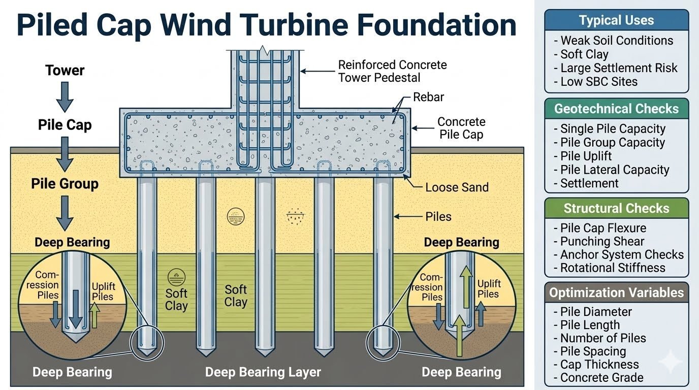
The load path in these complex geotechnical systems requires meticulous coordination. Gravity and lateral wind loads travel from the steel tower down through a reinforced concrete pedestal, spread across a massive concrete pile cap, and distribute dynamically into a subterranean pile group.
Key Engineering Takeaways
- Simultaneous resistance of compressive overloads and tension uplift forces under extreme wind overturning moments.
- Rigorous verification of single pile vertical capacity, group interaction effects, and long-term settlement limits.
- Advanced structural design of pile caps for high punching shear, flexural moments, and rotational stiffness.
- Comprehensive optimization of pile diameter, spacing, length, and concrete grade to minimize project costs.
Piled Cap Wind Turbine Foundation Load Transfer Mechanisms
Designing a wind turbine foundation requires understanding extreme load reversals. The rotor-nacelle assembly generates massive horizontal thrust forces and overturning moments that dwarf the vertical dead weight of the tower itself. These loads must be channeled securely into the earth without inducing excessive rotation or structural distress.
The load path initiates at the wind turbine tower flange, transferring shear and bending moments directly into a reinforced concrete pedestal. This pedestal is heavily reinforced with vertical rebar dowels anchored deep into the underlying concrete pile cap. The pile cap acts as a thick rigid mat, distributing the concentrated pedestal reactions across a wider footprint.
Geotechnical Analysis and Load Distribution
Beneath the pile cap, the pile group interacts directly with soft clays and loose sands. Under wind loading, the moment creates a linear strain profile across the pile group. Piles on the windward side experience tension and uplift, while leeward piles undergo magnified compression loads.
Engineers must perform single-pile capacity calculations under combined axial and lateral loads. Skin friction in upper weak layers is often neglected, relying entirely on end bearing in deep rock or dense sand strata. Group efficiency factors, evaluated per ASCE guidelines, dictate reductions in capacity due to stress zone overlapping.
Critical Design Warning: Cyclic Fatigue & Soil Degradation
Wind turbines impart millions of cyclic load reversals over their operational lifespan. In saturated soft clays, this cyclic action induces pore pressure buildup, leading to stiffness degradation and progressive loss of skin friction.
Foundation designers must apply dynamic reduction factors and specify adequate embedment lengths into competent bearing layers to prevent long-term tilt or fatigue failure.
Structural Design of the Pile Cap
The concrete pile cap must be modeled as a thick plate or rigid block capable of resisting severe shear stresses and bending moments. Following ACI 318 provisions, deep beam shear and two-way punching shear around the pedestal and individual piles govern thickness selection.
Reinforcement detailing requires dense bottom mats to handle upward bending and extensive top mats to control thermal cracking in mass concrete pours. Shear reinforcement in the form of headed studs or closed stirrups is frequently required to satisfy punching shear demands without making the cap impractically thick.
Engineering Advantages
- Extends wind turbine constructability to sites with weak soils, soft clays, and very low surface bearing capacity.
- Provides robust resistance against extreme overturning moments through dedicated tension and compression pile pairs.
- Significantly limits total and differential settlements, protecting sensitive internal turbine alignment.
- Allows precise adjustment of foundation stiffness by varying pile diameter, length, and group geometry.
- Eliminates the massive excavation and soil replacement volumes required for shallow gravity foundations on soft ground.
Engineering Disadvantages
- Higher initial capital expenditure compared to standard shallow gravity spread footings on competent soil.
- Demands specialized heavy marine or land-based piling rigs, increasing site mobilization complexity.
- Requires extensive geotechnical subsurface investigation and load testing to confirm single and group pile capacities.
- Massive concrete volumes in the thick cap present significant thermal cracking risks during curing, requiring strict mix design control.
- Complex connection detailing between steel reinforcement, anchor cages, and driven or bored piles.
Soft Deltaic and Estuarine Clays
Coastal and river delta wind farms frequently feature thick deposits of soft, normally consolidated marine clays with meager undrained shear strengths. Piled cap foundations bypass these compressible strata entirely, transferring massive wind loads directly to deep underlying bedrock.
Offshore Transition Pieces and Nearshore Installations
Shallow water wind energy projects utilize heavy piled jacket and gravity-piled cap hybrids to anchor multi-megawatt turbines. The deep pile groups resist severe wave slamming and wind overturning forces in shifting seabed sands.
High-Seismicity Sites with Liquefaction Risk
In earthquake-prone regions characterized by loose, saturated sandy soils susceptible to liquefaction, shallow foundations fail catastrophically. Deep steel or concrete piles extend through the liquefiable layer to anchor firmly in stable non-liquefiable strata.
Repowering Sites with Existing Footprint Constraints
When upgrading older 1MW wind turbines to modern 5MW+ machines on the same plot, space limitations prevent enlarging shallow spread footings. High-capacity piled caps support the increased loads within a compact footprint.
Engineering Design Parameters for Piled Cap Wind Turbine Foundations
Designing a robust piled cap wind turbine foundation requires careful evaluation of various geotechnical and structural parameters to ensure long-term stability under severe dynamic wind loading. In my engineering practice, I rely heavily on empirical guidelines outlined in ASCE design manuals and API standards for offshore and onshore deep foundation design. The table below outlines the critical design parameters, standard notations, typical operational ranges, and governing design codes that every structural engineer must verify before finalizing the pile cap geometry and reinforcement layouts.
Variations in soil stiffness across the loose sand and soft clay strata directly influence the load-sharing characteristics between the concrete pile cap and the underlying pile group. Careful cross-referencing with ASTM soil testing standards ensures that the input parameters used in finite element models accurately reflect insitu geotechnical conditions. Review these values thoroughly to maintain compliance with ASCE structural safety factors.
| Parameter Description | Symbol / Notation | Typical Design Range | Governing Standard |
|---|---|---|---|
| Pile Diameter | d_p | 900 mm – 2000 mm | ASTM D25 |
| Pile Embedment Length | L_p | 25 m – 50 m | ASCE 7 |
| Pile Center-to-Center Spacing | S | 3.0d_p – 4.5d_p | ASTM D1143 |
| Concrete Cap Thickness | h_c | 2.5 m – 4.5 m | ACI 318 |
| Concrete Compressive Strength | f’_c | 35 MPa – 50 MPa | ACI 318 |
Note: All values must be verified against site-specific geotechnical borehole logs and dynamic turbine fatigue spectra.
Technical Mapping & Specifications Matrix
To ensure complete digital integration and advanced structural analysis, this entity specifications matrix maps the core physical parameters, governing equations, and material constants associated with piled cap wind turbine foundations. When modeling dynamic wind turbine loads through finite element platforms, engineers must accurately define structural interactions between the reinforced concrete pedestal, the thick concrete pile cap, and the deep friction-bearing pile group embedded within soft clay strata.
Every entity listed below correlates directly with established design provisions found in ASCE and ASTM documentation. Utilizing standardized nomenclature prevents modeling discrepancies during complex pushover and cyclic fatigue evaluations required for utility-scale wind energy installations.
| Entity Category | Parameter Name | Engineering Scope | Standard Reference |
|---|---|---|---|
| Geotechnical | Ultimate Skin Friction | Load transfer along pile shaft in soft clay | ASTM D1143 |
| Geotechnical | Tip Bearing Capacity | End bearing resistance in deep firm layer | ASTM D4945 |
| Structural | Punching Shear Resistance | Critical perimeter check around tower pedestal | ACI 318 |
| Structural | Rotational Stiffness | Foundation tilt control under cyclic wind moments | ASCE 7 |
| Dynamic | Natural Frequency | Avoiding resonance with rotor passing frequencies | IEC 61400 |
Reference: Data compiled from wind turbine manufacturer guidelines and international deep foundation design codes.
Site Verification Checklist for Piled Cap Foundations
Executing a flawless construction sequence for a wind turbine piled cap foundation requires rigorous quality control at every phase of the project. In my site supervision experience, overlooking minor detailing tolerances in reinforcement cages or pile positioning can lead to severe structural distress under cyclic overturning moments. I always mandate strict adherence to the verification workflow outlined below before any major concrete pour or heavy turbine assembly commences.
Ensure that all testing and inspection protocols comply with ASCE construction standards and ASTM material testing guidelines. The following structured checklist provides site engineers with actionable inspection checkpoints to guarantee absolute structural integrity.
Comprehensive Foundation Quality Assurance Checklist
-
Geotechnical Boring Verification: Confirm that soil strata depths, unconfined compressive strengths of soft clay layers, and loose sand relative densities match the design borehole logs prior to pile boring.
-
Pile Shaft Integrity Testing: Perform Low Strain Integrity Testing (ASTM D5882) and Cross-Hole Sonic Logging on 100 percent of drilled shafts to detect necking or inclusions.
-
Pile Head Embedment Check: Verify that pile reinforcement extends into the concrete pile cap by the specified development length to ensure effective tension and compression load transfer.
-
Anchor Cage Alignment: Inspect the embedded anchor ring and post-tensioning duct assemblies for levelness, rotational orientation, and spatial accuracy within millimeter tolerances.
-
Thermal Control Monitoring: Install thermocouple arrays within the massive concrete pile cap to monitor hydration temperatures and prevent thermal cracking during mass pouring.
-
Static Load Testing: Execute full-scale axial compression and uplift load tests on sacrificial anchor piles in accordance with ASTM D1143 protocols.
Verification must be signed off by the lead geotechnical engineer and principal structural reviewer before proceeding to superstructure erection.
Field Case Study: Real-World Application
In a recent 3.4 MW onshore wind farm project situated across challenging coastal terrain characterized by 12 meters of very soft marine clay overlaying dense weathered sandstone, our engineering team encountered severe geotechnical limitations that ruled out conventional gravity foundations. Differential settlement risks and extremely low undrained shear strength values demanded a deep piled cap foundation solution capable of withstanding extreme cyclic wind overturning moments without excessive tilting or structural fatigue.
Engineering Problem Encountered
Initial preliminary designs utilizing a standard 18-pile group experienced excessive rotational deflection and localized tension overstressing under maximum 50-year wind gust events.
- Soft clay consolidation caused excessive immediate and long-term settlement predictions exceeding 50 mm limits.
- Cyclic overturning moments induced severe uplift forces on tension piles, threatening bond failure at the pile-soil interface.
- Inadequate lateral subgrade reaction in the upper loose sand stratum resulted in unacceptable lateral displacement at the tower base.
- Thermal crack formation risks escalated due to the massive 3.8-meter thick concrete cap pour required for shear transfer.
Proven Engineering Outcome
Optimizing the pile group configuration and implementing rigorous thermal curing controls successfully eliminated structural distress and secured long-term turbine stability.
- Redesigned the deep foundation to a optimized 24-pile arrangement with increased diameter to 1200 mm, reducing maximum pile compressive stress by 28 percent.
- Integrated corrosion-protected high-tensile steel rebars in uplift piles to safely transfer tension forces down to the bearing stratum.
- Implemented low-heat Portland cement combined with internal cooling pipes, restricting peak core temperatures below 65 degrees Celsius.
- Achieved measured rotational stiffness exceeding ASCE serviceability requirements, limiting permanent foundation tilt to less than 0.15 degrees over 10 years of operation.
Final Recommendation: For wind turbine installations on compressible soft soils, always couple detailed finite element soil-structure interaction analysis with comprehensive cyclic load testing to ensure robust long-term performance.
Frequently Asked Engineering Questions
How do we calculate maximum uplift load on tension piles under extreme wind overturning moments?
- Apply factored overturning moments divided by the effective pile group lever arm distance.
- Subtract buoyant self-weight of the concrete pile cap and embedded tower pedestal.
- Account for skin friction resistance reduction in tension compared to downward compression piles.
What are the key geotechnical failure modes evaluated for a piled cap wind turbine foundation?
- Single pile axial compression and tension pullout capacity based on soil shear strength.
- Pile group block failure capacity and differential settlement under cyclic wind loading.
- Lateral soil resistance and p-y curve analysis for pile shafts under horizontal shear.
How is punching shear controlled in thick concrete pile caps under high rotational stiffness?
- Verify critical perimeter sections at a distance of effective depth from the pedestal edge.
- Incorporate headed shear studs or closed stirrups if concrete shear capacity is exceeded.
- Ensure high-grade concrete (C40/50 or greater) to enhance diagonal tension resistance.
Why are steel H-piles or bored cast-in-place piles preferred over driven timber in wind farms?
- Steel H-piles and bored concrete piles offer superior tensile connection integrity.
- Drilled shafts eliminate driving refusal risks in dense intermediate strata.
- Reinforced concrete bored piles provide exceptional stiffness against lateral deflection.
What optimization parameters minimize concrete volume without compromising rotational stiffness?
- Optimize pile spacing to maximize the group moment of inertia while avoiding overly large cap diameters.
- Utilize tapered or stepped pile cap profiles to reduce dead weight at outer edges.
- Perform parametric finite element iterations varying pile count and cap thickness simultaneously.
Field Recommendation
Based on over two decades of heavy civil and industrial structural design experience, my direct engineering guidance for executing a piled cap wind turbine foundation in challenging soils involves the following actionable judgment calls:
- If site geotechnical reports indicate deep soft clay strata exceeding fifteen meters, select large-diameter bored cast-in-place piles rather than driven piles to eliminate ground heave risks and ensure precise vertical alignment tolerances.
- When cyclic wind overturning moments dominate the fatigue design, specify mechanical rebar couplers and headed shear reinforcement within the pedestal-to-cap junction to prevent progressive bond degradation and brittle shear failure.
- Always perform coupled soil-structure interaction (SSI) modeling instead of uncoupled rigid cap assumptions, because ignoring pile-head flexibility can severely underpredict rotational tilt and turbine operational frequency tuning.
- If high groundwater tables and aggressive soil chemistries are present, mandate sulfate-resistant cement (Type V or equivalent) along with a minimum 75 mm concrete cover over all pile reinforcement cages to guarantee the required 30-year design life.
- Prioritize pile spacing at a minimum of three times the pile diameter (3D) to mitigate group interference efficiency losses in loose sand layers during combined compression and cyclic lateral loading events.
Complete Course on
Piping Engineering
Check Now
Key Features
- 125+ Hours Content
- 500+ Recorded Lectures
- 20+ Years Exp.
- Lifetime Access
Coverage
- Codes & Standards
- Layouts & Design
- Material Eng.
- Stress Analysis
