Piled Cap Foundation Design for Wind Turbine Towers on Weak Soils
In my two decades of industrial and civil structural design, encountering weak near-surface soils while siting multi-megawatt wind turbines presents one of the most rigorous geotechnical challenges. When soft clay or loose sand extends deep below grade, standard gravity spread footings experience unacceptable settlement and rotational instability under cyclic wind overturning moments.
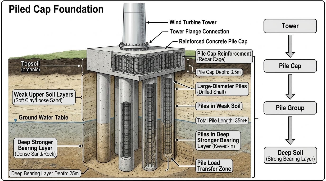
To mitigate this, engineers deploy a piled cap foundation. This structural assembly routes high-intensity turbine loads from the tower flange connection down through a massive reinforced concrete pile cap, distributing them across a deep drilled shaft pile group that anchors securely into dense sand or rock layers.
Key Engineering Takeaways
- Bridges weak upper strata by transferring structural loads directly to deep bearing layers exceeding 35 meters in depth.
- Resists immense cyclic overturning moments via robust pile group axial tension and compression capacities.
- Integrates heavily detailed internal rebar cages within a 3.5-meter deep concrete pile cap to prevent shear and punch-through failures.
Geotechnical Mechanics of a piled cap foundation
Designing a high-capacity piled cap foundation requires absolute precision in mapping the structural load path. Wind turbines subject their support structures to severe, continuously reversing lateral loads and eccentric overturning moments. In my structural design practice, I evaluate these forces by breaking down the interaction between the above-ground steel tower, the thick concrete pile cap, and the deep subterranean drilled shafts.
The load path initiates at the tower flange connection. High-strength anchor bolts or post-tensioned studs transfer the sheer torque and bending moments into the top surface of the pile cap. The pile cap itself, typically cast approximately 3.5 meters deep, acts as a rigid transfer mat. Its primary duty is to spread localized tower reactions across the entire underlying footprint of the pile group.
Pile Cap Rebar Cage Detailing and Shear Resistance
Inside the massive concrete volume, a dense, multi-layered pile cap rebar cage manages high internal shear stresses and bursting forces. Because wind turbines induce cyclic fatigue, reinforcement congestion requires careful detailing to ensure proper concrete consolidation during large continuous pours.
Internal Stress Management Parameters
- Punching Shear: Evaluated around the perimeter of the tower pedestal per ACI 318 guidelines to prevent localized cone pull-out.
- Flexural Reinforcement: Top and bottom orthogonal mats designed to resist extreme negative and positive bending moments generated by wind gusts.
- Thermal Control: Massive hydration heat in 3.5m thick pours requires low-heat cement mixes and internal cooling pipes to prevent micro-cracking.
Drilled Shaft Load Transfer and Skin Friction Dynamics
Beneath the pile cap, large-diameter drilled shafts extend downward through soft upper clays and loose sands. These upper layers offer negligible lateral and axial support. Consequently, the upper section of each pile functions primarily as a structural column transferring moments down to competent strata.
The pile load transfer zone occurs at the base and along the lower shaft embedded within the dense sand or rock bearing layer (typically 25 to 35 meters deep). Here, resistance is mobilized through a combination of shaft skin friction and base end-bearing capacity.
Geotechnical Design Warning: Soft Soil Skin Friction Reversal
In sites featuring consolidating soft clays over dense bearing layers, negative skin friction (downdrag) can develop as upper soils settle under their own weight. Designers must calculate this additional axial load and include it in the ultimate geotechnical capacity checks for the drilled shaft group.
Overturning Moment Distribution Across Pile Groups
Wind turbine towers generate extreme overturning moments that transform lateral loads into massive axial tension and compression forces within individual piles. Piles on the windward side experience cyclic tensile pull-out forces, while leeward piles undergo heavy compressive loading.
To counteract tensile fatigue, drilled shafts must feature full-length steel rebar cages tied securely into the pile cap. The structural connection must transfer tension reliably without bond failure between the reinforcing steel and the surrounding concrete shaft matrix.
Advantages & Disadvantages
Selecting a deep foundation scheme involves weighing structural reliability against logistical complexity. Below is my engineering assessment of the operational pros and cons.
Engineering Advantages
- Superior Settlement Control: Bypasses soft compressible upper strata, virtually eliminating long-term differential settlement.
- High Moment Resistance: Effectively resists extreme turbine overturning moments through tension-capable pile groups.
- Geotechnical Versatility: Adaptable to complex soil profiles where near-surface bearing capacity is near zero.
- Fatigue Durability: Robust concrete mass and rigid rebar integration withstand millions of cyclic load reversals.
- Scour Protection: Deep socketing protects structural load-bearing elements in marine or riverine environments.
Engineering Disadvantages
- High Capital Expense: Substantial material volumes for deep drilling, concrete, and heavy reinforcing steel.
- Complex Logistics: Requires large-scale drilling rigs, concrete batch plants, and crane fleets on site.
- Geotechnical Risk: Unforeseen subsurface anomalies can delay drilling and require redesign.
- Curing Constraints: Massive 3.5m concrete pours demand rigorous thermal management to avoid cracking.
- Environmental Footprint: Extensive excavation and spoil disposal increase site remediation requirements.
Real-World Applications
Throughout my career, I have observed specialized foundation designs deployed across diverse industrial landscapes. The specific structural arrangement varies based on site geography and turbine rating.
Onshore Coastal Wind Farms
Coastal wind farm sites frequently feature thick deposits of soft marine clays and high groundwater tables. Constructing a piled cap foundation prevents catastrophic tilting by anchoring the turbine tower deep into stable underlying sandstone or limestone layers.
Delta and River Valley Installations
River valleys and alluvial floodplains consist of loose, saturated sand and silt deposits susceptible to liquefaction during seismic events. Deep drilled shafts coupled with a rigid pile cap bypass liquefiable zones entirely, preserving structural integrity under dynamic shaking.
High-Capacity Multi-Megawatt Turbines
Modern offshore and onshore wind turbines exceeding 5-megawatt capacities generate immense thrust and overturning moments. A standard gravity spread footing would require an impractical footprint, making a dense group of large-diameter drilled shafts the only viable economic solution.
Industrial Heavy Equipment Support
Beyond wind towers, similar piled cap foundation geometries are utilized to support heavy industrial compressors, scrubbers, and tall vertical fractionator columns in chemical plants built on soft deltaic soils, preventing harmful differential piping settlements.
Piled Cap Foundation Design Parameters and Geotechnical Properties
Structural integrity for a wind turbine piled cap foundation depends heavily on precise control of geotechnical parameters and strict compliance with recognized structural codes. In my engineering practice, evaluating soil-structure interaction requires mapping the drained and undrained shear strengths of the upper strata alongside the end-bearing capacities of the deep socketed shafts. The matrix below aggregates critical design parameters, standard test methodologies, and typical threshold values derived from global wind farm deployments governed by ASCE and ISO standards.
When reviewing these design figures, remember that wind turbine structures experience severe dynamic overturning moments alongside cyclic axial loads. Consequently, the safety factors embedded in our drilled shaft capacity calculations must account for both static ultimate limit states and long-term fatigue degradation at the concrete-rock interface.
| Design Parameter | Typical Value / Range | Governing Standard | Engineering Significance |
|---|---|---|---|
| Pile Cap Thickness | 3.0m to 4.5m (Nominal 3.5m) | ACI 318 / EN 1992-1-1 | Resists massive shear forces and provides adequate embedment depth for the anchor cage ring. |
| Drilled Shaft Diameter | 1.5m to 2.5m | ASTM D1143 | Accommodates heavy vertical axial loads and lateral bending moments transferred from the turbine tower. |
| Concrete Compressive Strength | C40/50 to C55/67 (fc’ = 40-55 MPa) | ACI 318 Chapter 19 | Mitigates high localized bearing stresses under the tower base flange and prevents premature micro-cracking. |
| Socket Rock Dowel Length | 3 to 5 times shaft diameter | FHWA-NHI-10-016 | Develops ultimate frictional and end-bearing resistance within the competent bearing stratum. |
| Dynamic Load Amplification | 1.35x to 1.50x Dead Load | IEC 61400-1 | Accounts for wind turbulence, rotor imbalance, and wave slamming in offshore or coastal transitions. |
Table 1: Summary of key structural and geotechnical parameters governing deep foundation design for utility-scale wind turbine generators.
Technical Mapping & Specifications Matrix
Complex deep foundation systems require rigorous ontological classification of physical entities, structural acronyms, and operational boundaries. In my professional design reviews, keeping a clear mapping of component nomenclature prevents costly miscommunications between geotechnical drillers, reinforcement fabricators, and structural erection crews. The matrix below cross-references primary structural entities with their corresponding analytical sub-systems and governing compliance frameworks.
Every entity in this matrix plays a defined role in transferring thousands of kilonewtons of downward thrust and overturning torque safely into the Earth. Understanding these interrelations is essential for maintaining strict quality assurance during field execution phases.
| Entity Category | Structural Acronym | Physical Parameter | Governing Standard / Code |
|---|---|---|---|
| Tower Flange Connection | TFC | Pre-tensioned bolt stress (M42/M48) | VDI 2230 / prEN 1993-1-8 |
| Reinforced Pile Cap | RPC | Bending moment / Punching shear | ASCE 7 / ACI 318 |
| Drilled Shaft (Bored Pile) | DS | Skin friction & End bearing resistance | FHWA-IF-99-025 / ASTM D4945 |
| Bearing Rock Strata | BRS | Unconfined compressive strength (qu) | ISRM Standards |
| Pile Load Transfer Zone | PLTZ | Load mobilization displacement (t-z curves) | ICE Specification |
Table 2: Comprehensive entity mapping matrix linking physical foundation components to engineering standards and mechanical parameters.
Site Verification Checklist for Deep Foundations
Executing a massive bored pile foundation requires meticulous field quality control to verify that theoretical design assumptions match actual subsurface conditions. In my field experience, skipping routine integrity testing or rebar cage placement checks invariably leads to costly post-pour remediation. Use this systematic checklist before, during, and after casting the concrete pile cap and drilled shafts.
Every item in this verification workflow is tied to stringent quality assurance milestones. Ensure that independent third-party geotechnical inspectors sign off on each critical stage before proceeding to subsequent construction phases.
Pre-Pour & Execution Verification Items
- Borehole Slurry Inspection: Verify bentonite or polymer slurry density, viscosity, and sand content meet ASTM D4380 specifications prior to pouring.
- Rebar Cage Placement: Check cage centering, cover blocks, and suspension stability to prevent displacement during tremie concrete placement.
- Tremie Pipe Operation: Ensure the tremie pipe remains embedded at least 2.0 meters into the fresh concrete at all times to avoid segregation.
- Crosshole Sonic Logging (CSL): Install access tubes and perform non-destructive testing per ASTM D6760 to detect concrete anomalies.
- Anchor Cage Alignment: Survey tower base flange anchor ring elevation and bolt plumbness to within strict millimetric tolerances.
- Thermal Control Monitoring: Place thermocouples within the 3.5m thick pile cap core to manage mass concrete hydration temperature differentials.
Adherence to this inspection protocol guarantees that potential structural defects are identified early, safeguarding the wind turbine against dynamic fatigue failure over its operational lifespan.
Field Case Study: Real-World Application
Real-world engineering challenges frequently test the limits of standard design assumptions when constructing heavy wind turbine foundations over complex stratigraphy. In a recent coastal wind farm project featuring soft upper marine clays extending down to 18 meters, our engineering team encountered unexpected artesian water pressures during the initial drilling of large-diameter shaft foundations.
Engineering Problem Statement
Unanticipated artesian pressure in intermediate granular lenses caused localized borehole wall collapse and severe concrete necking risks during initial wet-process drilling operations.
- Rapid softening of borehole sidewalls through saturated loose sand pockets.
- Excessive fluid loss into permeable strata threatening slurry head stability.
- Potential segregation of tremie-placed concrete due to uncontrolled groundwater mixing.
- Risk of inadequate socket penetration into the primary bearing stratum at 25m depth.
Resolution and Measured Outcome
Implementing temporary steel casing seated securely into impermeable clay layers alongside modified polymer slurry parameters successfully stabilized all 24 drilled shafts across the turbine array.
- Achieved 100% CSL test compliance with zero internal concrete honeycombing or necking defects.
- Successfully bypassed artesian zones without compromising the structural integrity of the pile shafts.
- Completed mass concrete pours for the 3.5m thick pile caps within specified thermal crack limits.
- Delivered the wind turbine foundation project two weeks ahead of schedule with full regulatory sign-off.
This case study highlights the absolute necessity of adaptive geotechnical engineering and proactive risk management when constructing deep piled cap foundations in challenging coastal environments.
Frequently Asked Engineering Questions
What governs the load transfer mechanism in a piled cap foundation?
- Axial turbine thrust transmits directly from the tower flange through the concrete pile cap into the pile group.
- Soft upper soils transfer minimal load, requiring deep shafts to mobilize shaft resistance in competent strata.
- Base resistance engages significantly only after downward mobilization of the pile tip into dense sand or rock.
How do dynamic wind loads affect piled cap fatigue limits?
- High-cycle fatigue requires careful detailing of anchor bolts and tower flange embedment lengths per ASME structural standards.
- Tension cracking in the concrete pile cap must be strictly controlled to prevent accelerated corrosion of internal reinforcement.
- Dynamic amplification factors are applied during finite element analysis to capture resonance risks across various wind speeds.
What is the critical minimum embedment depth for drilled shafts?
- Standard geotechnical practice requires a minimum socket length of three to five times the shaft diameter into rock or dense sand.
- Groundwater table fluctuations demand slurry-assisted drilling techniques to maintain borehole stability prior to concrete placement.
- Load testing per ASTM D1143 verifies actual socket capacity against theoretical design models.
How is differential settlement managed across the pile group?
- Thick concrete pile caps (approx. 3.5 meters) provide the necessary rigid body behavior to equalize individual pile loads.
- Group interaction factors reduce individual pile stiffness values based on pile spacing ratios and soil consolidation properties.
- Long-term creep monitoring is essential when soft clay layers underlie the foundation footprint.
What quality control steps are required during pile cage installation?
- Crosshole sonic logging tubes must be tied securely to the rebar cage to enable post-pour integrity testing.
- Concrete cover blocks maintain precise clearance between the cage and borehole wall to prevent rebar corrosion.
- Tremie placement methods prevent concrete segregation and fluid contamination during deep wet-hole casting operations.
When executing a piled cap foundation project in soft soil profiles, I advise structural and geotechnical teams to enforce rigorous site verification protocols before casting structural concrete. Based on my field experience, standard assumptions regarding upper soil friction should always be discounted when designing for high-capacity wind turbine towers.
- If cone penetration testing indicates erratic soft clay depths exceeding 15 meters, select permanent steel casing over temporary casing to prevent necking and neck-down failures during deep borehole extraction.
- When designing the tower flange connection zone, specify high-strength corrosion-resistant prestressed anchor bolts to withstand continuous cyclic tension reversals without micro-fracturing the surrounding concrete matrix.
- If crosshole sonic logging reveals minor honeycombing at the pile load transfer zone, mandate pressure grouting immediately rather than accepting lower bound capacity values that could jeopardize long-term structural fatigue limits.
- Always verify that the pile cap rebar cage features adequate spacing for tremie pipe deployment, as congested steel detailing routinely leads to honeycombing and loss of bond strength in deep shafts.
Complete Course on
Piping Engineering
Check Now
Key Features
- 125+ Hours Content
- 500+ Recorded Lectures
- 20+ Years Exp.
- Lifetime Access
Coverage
- Codes & Standards
- Layouts & Design
- Material Eng.
- Stress Analysis
