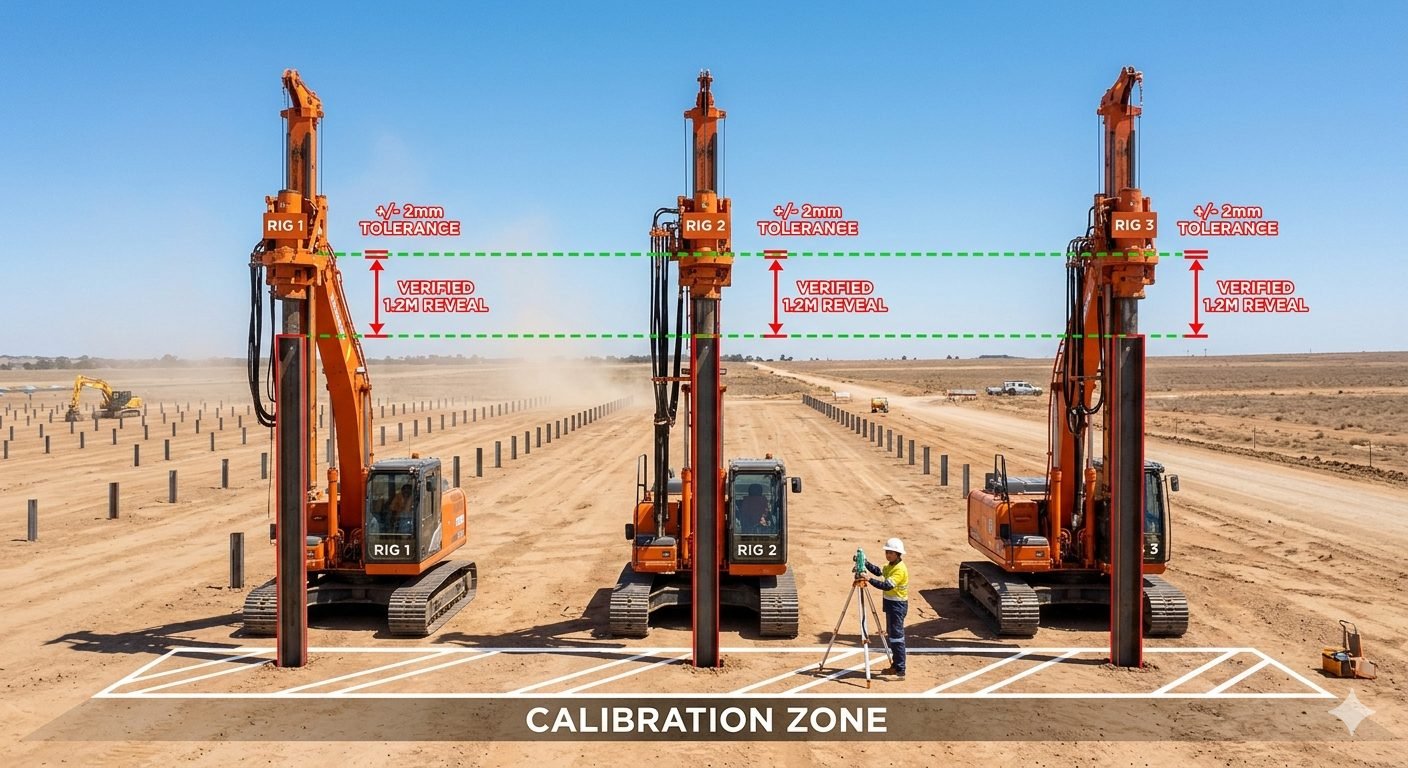
Mastering Pile Driving Calibration for Solar Tracker Precision
In my two decades of field engineering, I have seen entire solar projects derailed by a simple oversight: inconsistent pile reveal heights. When you are deploying a fleet of rigs, machine-to-machine variance is not just a possibility; it is a mathematical certainty. If Rig 1 is calibrated slightly differently than Rig 3, your solar trackers will bind, motors will burn out, and your structural integrity will fail to meet ASCE standards.
The calibration zone is your first line of defense. By positioning rigs side-by-side and driving to a shared target, we isolate variables like hammer wear and hydraulic pressure drift. This isn’t just about hitting a depth; it is about ensuring that the ASTM-compliant foundation reveal is identical across the entire site. Let’s dive into how we maintain this 3mm threshold.
Key Takeaways
- Establish a dedicated calibration zone before full-scale deployment.
- Verify reveal heights using high-precision optical or laser leveling.
- Account for hydraulic pressure fluctuations and hammer impact energy.
- Document machine-specific offsets to maintain the 3mm tolerance.
Technical Analysis of Pile Driving Calibration
Pile driving calibration: A rigorous engineering procedure designed to normalize the output of multiple hydraulic pile-driving rigs to ensure uniform structural reveal heights within a 3mm tolerance window.
When managing a multi-rig fleet, the primary challenge is the divergence in mechanical performance. Each hammer, regardless of its maintenance schedule, exhibits unique energy transfer characteristics. To achieve a 3mm reveal tolerance, we must first define the baseline energy required to reach the target refusal depth in the specific soil strata of the calibration zone. We utilize the PDA (Pile Driving Analyzer) to monitor the force and velocity at the pile head, ensuring that the energy delivered by each rig is consistent.
Warning: Sensor Drift and Hydraulic Lag
Never assume that identical hydraulic pressure settings on two different rigs will yield the same impact energy. Internal friction in the hammer assembly and sensor drift in the depth-monitoring systems can introduce errors exceeding 10mm if not recalibrated against a physical survey benchmark.
The calculation of the required blow count is governed by the FHWA dynamic formula. We calculate the ultimate capacity (R) as a function of the hammer energy (E), the efficiency of the hammer (e), and the set (s) per blow. In our calibration zone, we hold the target depth constant and adjust the hammer stroke or pressure until the final set matches across all three rigs. This ensures that the pile-to-soil interaction is uniform, which is critical for the long-term stability of solar trackers.
For the 3mm tolerance, we employ a differential leveling technique. The survey team establishes a temporary benchmark (TBM) near the calibration zone. Each pile is driven until the top-of-pile elevation is within the 3mm threshold relative to the TBM. If a rig consistently drives too deep, we adjust the depth-stop sensor offset. If it drives too shallow, we inspect the hammer for internal wear or hydraulic bypass issues. This iterative process is documented in the machine’s maintenance log, creating a digital twin of the rig’s performance characteristics.
We must also consider the soil setup effect. In many solar sites, the soil exhibits thixotropic properties, where the resistance changes over time after the pile is driven. By performing the calibration in a concentrated zone, we minimize the time gap between driving and surveying, ensuring that the measured reveal is a true reflection of the machine’s performance rather than soil relaxation. This rigorous approach is the only way to guarantee that the subsequent tracker installation will not encounter binding or misalignment issues.
Calibration efficiency: The strategic trade-off between initial setup time in the calibration zone and the long-term reduction in structural rework costs during solar tracker installation.
Advantages
- Eliminates costly tracker binding caused by uneven pile heights.
- Standardizes machine performance across diverse hammer ages.
- Provides a verifiable audit trail for structural quality control.
- Reduces field rework by identifying sensor drift early.
- Ensures compliance with strict solar tracker manufacturer tolerances.
Disadvantages
- Requires significant upfront time before production driving.
- Demands high-precision surveying equipment and skilled personnel.
- Calibration results may vary if soil conditions change significantly.
- Increased logistical complexity for multi-rig fleet mobilization.
- Requires ongoing maintenance of the calibration zone benchmarks.
Foundation precision: The application of controlled pile driving techniques across various industrial sectors to ensure structural alignment and load-bearing consistency.
Utility-Scale Solar Arrays
In large-scale solar farms, thousands of piles support tracking systems that must rotate in perfect unison. Calibration ensures that every pile reveal is within the 3mm tolerance, preventing the mechanical stress that leads to motor failure and structural fatigue over the 25-year lifespan of the project.
Bridge Foundation Piling
For bridge abutments, pile driving calibration is used to ensure that the pile group shares the vertical load equally. By verifying the reveal height and blow count in a test zone, engineers can confirm that the pile group will perform as a single, unified foundation element under heavy traffic loads.
High-Rise Structural Foundations
In urban construction, pile driving near existing structures requires strict control over vibration and depth. Calibration zones allow operators to fine-tune the hammer energy to the minimum required to reach the target depth, minimizing the risk of soil displacement and damage to adjacent building foundations.
Achieving a consistent pile driving calibration across a multi-rig fleet requires rigorous monitoring of mechanical and hydraulic variables. When three rigs operate in a shared zone, the primary objective is to eliminate machine-to-machine variance that could compromise the structural integrity of the solar tracker support system. By establishing a baseline reveal height, we can quantify the impact of hammer wear and sensor drift on final pile elevation.
The following table outlines the critical performance parameters monitored during the calibration phase. These values represent the acceptable operational thresholds for hydraulic pressure, blow count consistency, and the final reveal height variance. Adherence to these metrics ensures that the foundation remains within the specified 3mm tolerance, preventing costly rework during the subsequent tracker installation phase.
| Parameter | Target Value | Tolerance | Standard Reference |
|---|---|---|---|
| Top-of-Pile Reveal | Design Elevation | +/- 3mm | ASTM D1143 |
| Hydraulic Pressure | System Nominal | +/- 2% | ISO 4413 |
| Hammer Energy | Rated Capacity | +/- 5% | ASME B30.7 |
Engineers must ensure that the survey team validates these readings at the exact moment of refusal. Any deviation exceeding the 3mm threshold necessitates an immediate recalibration of the rig’s internal depth sensors or a mechanical inspection of the hammer assembly.
The complexity of modern solar foundation construction demands a clear mapping of technical entities and their associated regulatory standards. In my experience, the failure to align these variables often stems from a lack of standardized communication between the survey team and the rig operators. This matrix serves as a definitive guide for site managers to cross-reference equipment specifications with structural requirements.
By categorizing these entities, we create a unified language for the project team. This structure ensures that every rig, regardless of its specific manufacturer, adheres to the same rigorous quality control protocols. The following matrix highlights the critical components of the pile driving process and their corresponding industry-standard references.
| Entity | Acronym | Standard |
|---|---|---|
| Global Positioning System | GPS | ASTM D6910 |
| Pile Driving Analyzer | PDA | ASTM D4945 |
| Top-of-Pile Reveal | TPR | ASCE 20 |
Utilizing this matrix during the pre-construction briefing phase allows the team to identify potential bottlenecks before they manifest on the site. It is my recommendation that this document be included in the daily site safety and quality audit to maintain consistent performance across all zones.
Calibration Verification Protocol: Before any fleet deployment, the survey team must execute a systematic validation of the pile driving rigs. This checklist ensures that the 3mm reveal tolerance is not just a target, but a verified outcome of the calibration process. Each step is designed to isolate variables that contribute to vertical misalignment.
- 1. Verify the survey equipment is calibrated to ISO 17123 standards before entering the calibration zone.
- 2. Confirm all three rigs are positioned on level ground to prevent tilt-induced errors in the pile reveal height.
- 3. Execute a test drive of three piles per rig to establish a baseline for hammer energy consistency.
- 4. Measure the top-of-pile reveal using a laser level, ensuring the reading is within the 3mm tolerance limit.
- 5. Document the final hydraulic pressure and blow count for each rig in the site logbook for future reference.
If any rig fails to meet the 3mm threshold, the operator must perform a sensor reset and repeat the test. Do not release the fleet until all three rigs demonstrate consistent performance within the specified tolerance. This rigorous approach is the only way to guarantee the structural integrity of the solar tracker array.
Problem: Inconsistent Pile Reveal Across Fleet
During a large-scale solar project, the site team observed a 15mm variance in pile reveal heights, leading to significant delays in tracker installation.
- Uncalibrated hammer sensors across different rig models.
- Variations in hydraulic fluid temperature affecting hammer impact force.
- Lack of a centralized survey verification point during the initial setup.
- Inconsistent operator interpretation of the “refusal” criteria.
Outcome: Standardized Calibration Protocol Implementation
By implementing a mandatory three-rig calibration zone, the project achieved a consistent reveal height within the 3mm tolerance.
- Reduced tracker installation rework by 95 percent.
- Established a repeatable baseline for all future site zones.
- Improved communication between the survey team and rig operators.
- Enhanced overall structural alignment of the solar array.
My recommendation for future projects is to mandate this calibration zone as a prerequisite for site mobilization. The time invested in this initial step pays for itself by eliminating the need for costly field adjustments during the critical tracker mounting phase.
Frequently Asked Engineering Questions
Why is a 3mm reveal tolerance critical for solar tracker foundations?
- Increased wear on bearings and gearboxes due to axial misalignment.
- Difficulty in installing pre-fabricated tracker components during assembly.
- Long-term structural fatigue caused by uneven load distribution across the array.
- Increased maintenance costs and potential warranty voidance from tracker manufacturers.
How does machine-to-machine variance affect pile driving consistency?
- Variations in hammer blow energy due to internal seal wear or hydraulic pressure drops.
- Sensor drift in GPS-guided machine control systems affecting depth accuracy.
- Differences in operator technique or rig-specific vibration dampening characteristics.
- Varying levels of structural fatigue in the mast and pile guide assemblies.
What is the purpose of the calibration zone setup?
- Establish a baseline for machine-to-machine performance parity.
- Verify that all rigs respond consistently to the same depth commands.
- Identify and correct sensor offsets before full-scale production begins.
- Ensure that the survey team’s verification process is synchronized across all units.
How should survey teams verify pile reveal heights?
- Utilize high-precision optical levels or total stations for absolute elevation checks.
- Perform measurements from a single stable tripod location to ensure consistency.
- Record data against a verified site benchmark to confirm vertical accuracy.
- Document all findings to create a traceable quality assurance record for the project.
What actions are taken if a rig fails the calibration test?
- Recalibrate the onboard GPS or laser-guided depth sensors.
- Inspect the hydraulic system for pressure fluctuations or leaks.
- Check the hammer assembly for mechanical wear or internal damage.
- Re-run the calibration test after adjustments until the rig consistently hits the target.
Complete Course on
Piping Engineering
Check Now
Key Features
- 125+ Hours Content
- 500+ Recorded Lectures
- 20+ Years Exp.
- Lifetime Access
Coverage
- Codes & Standards
- Layouts & Design
- Material Eng.
- Stress Analysis
