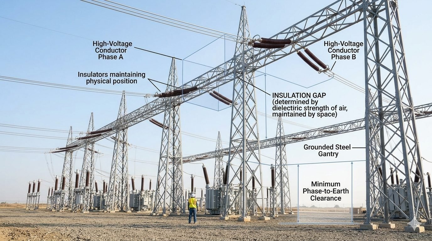
Calculating Phase to Phase Clearance for High-Voltage Gantries
In my two decades of experience working on high-voltage substation design, I have learned that the air gap is the most critical component of any gantry system. While we often focus on the structural steel or the mechanical tension of the conductors, the invisible dielectric barrier between Phase A and Phase B is what keeps the system operational. If this clearance is compromised, the result is an immediate arc flash, leading to catastrophic equipment failure and significant safety risks for site personnel.
Calculating these distances is not merely about following a table; it is about understanding the interaction between atmospheric conditions, switching surges, and the specific voltage levels of your installation. In this guide, I will walk you through the fundamental principles of maintaining these clearances to ensure your substation remains compliant and safe.
Key Takeaways
- Understand the dielectric strength of air under varying humidity and pressure.
- Apply IEC 60071 standards to determine minimum phase-to-phase clearance.
- Differentiate between lightning impulse and switching impulse withstand requirements.
- Identify the impact of altitude correction factors on air gap performance.
Technical Analysis of Phase to Phase Clearance
Phase to phase clearance: The required spatial separation between conductors to withstand the potential difference between phases, calculated based on the highest voltage for equipment and the insulation coordination requirements of IEC 60071.
When designing high-voltage gantries, the primary challenge is ensuring that the air gap remains non-conductive under all operating conditions. The dielectric strength of air is approximately 30 kilovolts per centimeter under ideal conditions, but this value drops significantly in real-world environments due to humidity, pollution, and electrode geometry. My approach always begins with the determination of the Required Withstand Voltage (RWV), which includes both the power frequency voltage and the transient overvoltages caused by switching or lightning strikes.
The calculation process involves determining the minimum clearance (d) based on the formula d = (U / E) * K, where U is the voltage stress, E is the critical breakdown field strength, and K is the safety factor. In practice, we refer to the tables provided in IEC 60071-2, which categorize equipment into specific insulation levels. For a 400kV system, the phase-to-phase clearance is significantly larger than the phase-to-earth clearance because the potential difference between two phases is higher than the potential between a phase and the grounded gantry.
I often see junior engineers confuse phase-to-earth and phase-to-phase requirements. The phase-to-earth clearance is governed by the line-to-neutral voltage, whereas the phase-to-phase clearance must account for the line-to-line voltage, which is higher by a factor of the square root of three. Furthermore, the geometry of the conductor bundle—whether it is a single conductor or a quad-bundle—affects the electric field distribution. A larger bundle diameter generally results in a more uniform field, which can allow for slightly more optimized clearances compared to a thin, single conductor that creates high field concentrations at the surface.
To verify these designs, we utilize finite element analysis (FEA) to map the electric field lines around the gantry. If the field intensity exceeds the breakdown threshold of air at any point between the phases, the clearance must be increased. This is particularly important at the jumper loops and the dead-end assemblies where the conductors are closest to the steel structure. Always ensure that the physical spacing accounts for the maximum swing of the conductors during high-wind events, as the dynamic clearance is what truly dictates the safety of the installation.
Design optimization: The process of balancing physical footprint, material costs, and electrical safety margins to achieve a compliant and cost-effective high-voltage gantry configuration.
Advantages
- Ensures long-term operational reliability by preventing arc-over events.
- Provides a clear, standardized framework for safety inspections.
- Allows for predictable maintenance cycles based on insulation degradation.
- Reduces the risk of catastrophic failure during transient overvoltage events.
- Facilitates easier integration of future capacity upgrades.
Disadvantages
- Requires larger physical footprints, increasing land acquisition costs.
- Increases the structural steel weight due to wider gantry spans.
- Higher material costs for longer insulator strings and cross-arms.
- Complex design requirements for high-altitude or high-pollution sites.
- Increased wind loading on the wider structural assemblies.
Industrial implementation: The practical application of IEC 60071 clearance standards across various high-voltage infrastructure projects to ensure grid stability and personnel safety.
Transmission Substation Gantry Design
In large-scale transmission substations, maintaining phase-to-phase clearance is the primary driver for the layout of the busbar system. Engineers must ensure that the rigid busbars are spaced sufficiently to prevent flashovers during switching operations, which are common in these high-traffic nodes.
High-Voltage Switchyard Expansion
When upgrading existing switchyards to higher voltage levels, the existing gantry structures often become the limiting factor. We must carefully calculate the new required clearances and often replace existing insulators with longer strings or install phase spacers to maintain compliance without rebuilding the entire structure.
Renewable Energy Interconnection Points
Wind and solar farms often require dedicated collector substations to step up voltage for grid injection. These sites are frequently located in remote, high-altitude areas where the air density correction factors become a critical part of the phase-to-phase clearance calculation to prevent insulation failure.
Determining the correct phase-to-phase clearance for high-voltage gantries requires strict adherence to IEC 60071 standards. These values are derived from the rated lightning impulse withstand voltage and the specific altitude correction factors applicable to the site. In my experience, engineers must account for both the switching impulse and the lightning impulse withstand levels, as the governing factor often shifts depending on the system voltage level.
The following table outlines typical minimum phase-to-phase clearance values for standard air-insulated substation (AIS) configurations. These values assume standard atmospheric conditions at sea level. When designing for high-altitude environments, you must apply the altitude correction factor, which typically increases the required physical gap by approximately 1.25 percent for every 100 meters above 1000 meters elevation.
| System Voltage (kV) | Phase-to-Phase Clearance (mm) | Impulse Withstand (kV) |
|---|---|---|
| 145 | 1600 | 650 |
| 245 | 2400 | 1050 |
| 420 | 4100 | 1425 |
Always verify these dimensions against the specific project IEEE C37.30 or local utility specifications. Discrepancies between international standards and local grid codes are common, and the more conservative value must always govern the final design layout.
The structural integrity of a high-voltage gantry relies on the precise mapping of electrical parameters to physical dimensions. This matrix identifies the critical entities involved in maintaining phase-to-phase clearance, ensuring that dielectric stress remains within the limits defined by IEC 60071-2. By categorizing these variables, we can systematically evaluate the impact of environmental factors on the insulation coordination strategy.
Engineers should utilize this matrix during the preliminary design phase to ensure all clearance zones are accounted for in the 3D model. Each entity represents a potential failure point if the physical spacing is compromised by structural deflection, thermal expansion of conductors, or incorrect insulator string orientation.
| Entity | Parameter | Standard Reference |
|---|---|---|
| Dielectric Strength | Air Breakdown Voltage | IEC 60071 |
| Phase-to-Phase | Physical Air Gap | IEEE C37.30 |
| Gantry Steel | Phase-to-Earth Clearance | IEC 61936 |
Maintaining these parameters is not merely a design exercise but a requirement for operational safety. Any deviation from these specifications during construction requires a formal re-validation of the insulation coordination study to prevent flashover events.
Verifying phase-to-phase clearance on-site is the final line of defense against catastrophic insulation failure. Before energization, I conduct a rigorous inspection of the gantry assembly to ensure that the as-built dimensions match the approved design drawings. Even minor deviations in insulator string length or conductor sag can reduce the effective air gap below the safety threshold defined by IEC 60071.
- 01. Verify that all insulator strings are correctly oriented to prevent swing-induced clearance reduction.
- 02. Confirm that the minimum phase-to-phase clearance is maintained at the point of maximum conductor sag.
- 03. Check that no temporary construction equipment or scaffolding encroaches on the required safety zone.
- 04. Validate that all phase-to-earth clearances are measured from the nearest grounded steel member.
- 05. Ensure that bird guards or other accessories do not bridge the required air gap.
During the site walk-down, I pay particular attention to the “swing” of the conductors under wind loading. A static clearance might look sufficient, but if the conductor can swing closer to the gantry steel or an adjacent phase, the dynamic clearance will be violated. Always document these measurements with calibrated laser rangefinders and cross-reference them with the original insulation coordination report. If any measurement falls within 5 percent of the minimum allowable limit, immediate corrective action is required to adjust the conductor tension or insulator string configuration.
Problem: Clearance Violation During Retrofit
During a 245kV substation upgrade, the installation of new, larger-diameter conductors resulted in a reduced phase-to-phase clearance due to unexpected sag characteristics.
- Conductor sag exceeded the initial design calculations by 150mm.
- The existing gantry geometry did not allow for further vertical adjustment.
- Wind-induced conductor swing threatened to violate the minimum air gap.
- The project schedule was at risk due to the potential for flashover.
Outcome: Successful Mitigation and Compliance
We resolved the issue by implementing a combination of rigid busbar sections and specialized insulator spacers to stabilize the conductor path.
- Installed rigid aluminum busbar sections to eliminate sag-related clearance issues.
- Utilized phase spacers to maintain the required air gap during high-wind events.
- Re-validated the insulation coordination study per IEC 60071.
- Achieved full compliance with zero operational downtime during the final commissioning.
My recommendation for similar projects is to perform a dynamic sag analysis early in the design phase, especially when upgrading existing infrastructure. Relying on static clearance values is insufficient when dealing with modern, high-capacity conductors that exhibit different thermal and mechanical properties than the legacy equipment they replace.
Frequently Asked Engineering Questions
How does IEC 60071 define the calculation for phase to phase clearance in high-voltage gantries?
The standard IEC 60071-1 establishes insulation coordination principles based on rated withstand voltages and atmospheric correction factors.
- Determine the peak switching and lightning impulse withstand voltages for the system.
- Apply deterministic or statistical methods to establish the minimum clearance distance.
- Account for environmental factors like altitude, humidity, and ambient temperature.
What is the physical relationship between the dielectric strength of air and conductor spacing?
The dielectric strength of air under standard conditions is approximately 3 kV/mm, which dictates the minimum physical gap required to prevent flashover.
- Non-uniform electric fields around stranded conductors lower the effective breakdown threshold.
- Transient overvoltages require proportional increases in physical spacing to maintain insulation integrity.
- Air density variations at high altitudes reduce dielectric strength, requiring larger clearance spans.
Why is the phase-to-earth clearance zone at a grounded steel gantry different from phase to phase clearance?
Grounded steel gantries represent a zero-potential plane, creating a highly asymmetric electric field compared to the field between two energized conductors.
- Phase-to-earth configurations typically exhibit lower breakdown voltages due to electrode geometry.
- Electrode configurations like rod-to-plane (conductor-to-gantry) require larger safety margins than conductor-to-conductor profiles.
- Standard design practices separate these zones to prevent localized corona discharge and subsequent phase-to-ground faults.
How do environmental correction factors affect open-air substation clearances?
Open-air installations must adapt nominal clearance values to account for local atmospheric conditions that degrade air insulation properties.
- Altitude corrections apply a multiplier for installations exceeding 1000 meters above sea level.
- Relative humidity and industrial pollution levels alter the surface conductivity of nearby insulators.
- Wind loading causes conductor swing, reducing the instantaneous physical gap below nominal design limits.
What safety standards govern the clearance distances for personnel working near energized gantries?
Personnel safety distances combine the electrical phase to phase clearance with an additional physical safety buffer to prevent accidental contact.
- The standard IEEE 1427 provides guidelines for establishing safe working boundaries around high-voltage equipment.
- Calculations incorporate the reach of maintenance personnel and the dimensions of standard tools.
- Local regulatory codes define the absolute limit of approach based on the system’s maximum operating voltage.
Complete Course on
Piping Engineering
Check Now
Key Features
- 125+ Hours Content
- 500+ Recorded Lectures
- 20+ Years Exp.
- Lifetime Access
Coverage
- Codes & Standards
- Layouts & Design
- Material Eng.
- Stress Analysis
