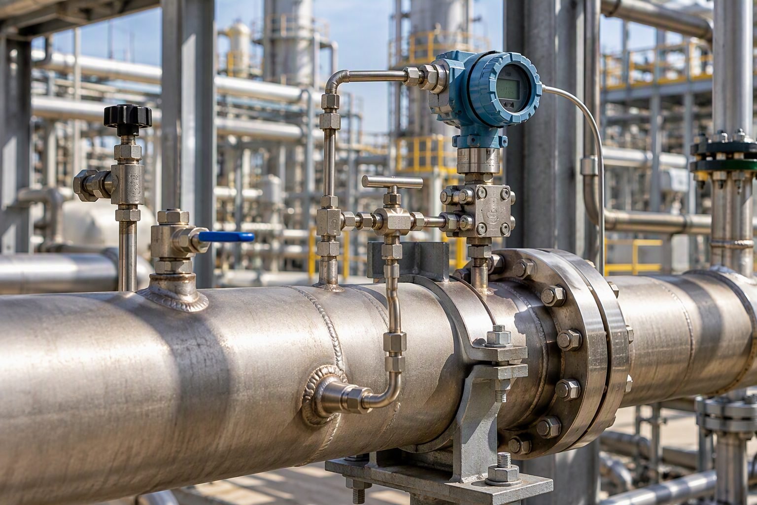
Orifice Plate vs Venturi Meter: Selecting DP Flow Technology
Flow Meter Selection: Choosing between an orifice plate and a venturi meter requires balancing permanent pressure loss, installation footprint, fluid entrained solids handling, and capital expenditures under ISO 5167 design criteria.
In my two decades of reviewing piping and instrumentation diagrams (P&IDs) for grassroots petrochemical complexes, differential pressure (DP) flow metering remains the backbone of custody transfer and utility balance. When specifying secondary instrumentation, junior engineers frequently struggle to justify whether a simple thin-plate restriction or a contoured differential producer best serves their fluid regime.
Selecting the wrong primary element leads to unrecoverable head loss, accelerated erosion from high-velocity slurry, or excessive straight-run piping requirements that inflate skid fabrication costs. Throughout this guide, I examine the fluid mechanics, permanent pressure loss formulas, and operational constraints governing ISO 5167 compliant flow metering.
Engineering Takeaways
- Orifice plates offer low capital cost and easy replacement but introduce high permanent pressure loss (typically 40% to 90% of differential pressure).
- Venturi tubes achieve exceptional hydraulic recovery (recovering up to 90% of differential head) due to their streamlined converging and diverging sections.
- Compliance with ISO 5167 mandates strict upstream and downstream straight-pipe lengths to eliminate swirl and velocity profile distortion.
- Fluid character dictates choice: clean gases favor orifice economy, whereas high-viscosity or solids-laden utilities demand venturi reliability.
Orifice Plate vs Venturi Meter: Fluid Mechanics and ISO 5167 Standards
Differential Pressure Fundamentals: Both primary elements operate on Bernoulli’s principle, constricting flow to create a measurable differential pressure proportional to the square of the volumetric flow rate.
Understanding the underlying fluid mechanics requires analyzing how velocity increases and static pressure drops across the restriction. For an orifice plate, the sharp-edged bore causes the flow stream to contract past the plate face, forming a vena contracta where velocity is maximal and static pressure is minimal.
Conversely, the venturi meter utilizes a smooth, gradual inlet cone (typically 21 degrees included angle) and an equally gradual outlet recovery cone (5 to 15 degrees included angle) to prevent flow separation and boundary layer detachment.
Governing Flow Rate Calculations
The theoretical mass flow rate (q_m) calculation under ISO 5167-1 incorporates the discharge coefficient (C), the expansibility factor (epsilon), the diameter ratio (beta = d/D), and the measured differential pressure (Delta p):
Where d is the orifice or venturi throat diameter, D is the internal pipe diameter, rho_1 is fluid density at upstream conditions, and C is empirically determined via the Reader-Harris/Gallagher equation for orifice plates or standard hydraulic profiles for venturi tubes.
Permanent Pressure Loss Analysis
Permanent pressure loss (Δ p_w) represents the unrecovered head consumed by fluid friction and turbulence eddies. In an orifice installation, downstream eddies dissipate almost all kinetic energy, resulting in permanent losses ranging from 40% to 90% of the measured differential pressure depending on the beta ratio.
For a venturi tube, the streamlined recovery cone allows boundary layers to reattach smoothly. Permanent pressure loss drops significantly, typically representing only 10% to 15% of the measured differential pressure, yielding massive pumping power savings over plant life cycles.
Operational Hazard: Cavitation and Choked Flow
When sizing DP flow meters for liquid services, localized pressure drop at the vena contracta or venturi throat must remain well above the fluid vapor pressure. Severe cavitation destroys internal bore edges, distorts coefficient calibration, and induces destructive pipe vibration.
Installation Geometry and ISO 5167 Piping Requirements
Flow meter accuracy depends entirely on upstream flow conditioning. ISO 5167 mandates specific straight lengths free of valves, bends, and reducers. An orifice plate downstream of a dual out-of-plane elbow requires up to 44 diameters of straight pipe unless a flow straightener is installed.
Venturi meters mitigate this constraint slightly due to their convergent inlet geometry, which dampens mild upstream swirl, yet they still demand rigorous adherence to ISO alignment tables to maintain uncertainty within plus or minus 0.5% to 1.5%.
Evaluation Matrix: Weighing the operational trade-offs between orifice plates and venturi meters ensures optimal alignment with plant utility budgets and process reliability targets.
Orifice Plate Advantages
- Extremely low initial procurement and replacement costs across all pipe sizes.
- Standardized geometry defined extensively in ISO 5167-2 without requiring individual wet calibration.
- Easy removal and inspection when housed inside specialized orifice flange unions with jacking screws.
- Flexible sizing: changing the beta ratio simply requires swapping the thin metal plate without modifying pipe spool lengths.
- Compatible with standard differential pressure transmitters and multi-variable manifold valve blocks.
Orifice Plate Disadvantages
- High permanent pressure loss results in increased compressor and pump energy consumption over time.
- Sharp upstream edge is highly susceptible to wear, rounding, and particulate abrasion in slurry service.
- Low turndown ratio (typically 3:1 to 4:1) without square-root extraction signal characterization.
- Prone to clogging and differential pressure port plugging when handling viscous or dirty fluids.
- Requires lengthy upstream straight pipe runs to establish fully developed turbulent velocity profiles.
Venturi Meter Advantages
- Outstanding hydraulic recovery, retaining up to 90% of differential pressure head.
- Self-cleaning internal profile prevents solids and particulates from accumulating at the throat.
- Tolerates much higher upstream fluid velocities and disturbed velocity profiles than orifice plates.
- Robust structural design with no sharp edges to degrade under erosive operating conditions.
- Long-term calibration stability minimizes measurement drift across harsh industrial cycles.
Venturi Meter Disadvantages
- Substantially higher initial capital expenditure and custom fabrication lead times.
- Bulky physical footprint and heavy weight require dedicated pipe support structures and lifting gear.
- Inability to alter the throat-to-pipe ratio in situ; replacing a worn venturi requires cutting out the entire spool.
- Challenging installation logistics in congested brownfield pipe racks and modular skid packages.
- Higher maintenance overhead if internal pressure tap piezometer rings become fouled.
Service Matching: Deploying differential pressure primary elements across diverse industrial sectors requires matching meter mechanical traits directly to fluid cleanliness and energy efficiency goals.
High-Pressure Natural Gas Transmission Pipelines
Natural gas custody transfer stations frequently utilize orifice meter runs configured in multi-tube parallel headers. The low cost and interchangeability of plates allow pipeline operators to easily recalibrate or swap bores when seasonal gas flow rates fluctuate.
Strict adherence to ISO 5167 and AGA-3 standards ensures financial accounting uncertainty remains below regulatory thresholds.
Boiler Feedwater and High-Pressure Steam Loops
Power generation facilities rely on forged venturi tubes to measure high-pressure boiler feedwater and superheated steam. Because pumping water against 180 bar boiler drum pressure consumes immense electrical power, minimizing permanent pressure loss is paramount.
The venturi recovery cone saves thousands of kilowatt-hours annually compared to restrictive orifice plates installed in the same header.
Petrochemical Slurry and Catalyst Handling Lines
Fluid catalytic cracking (FCC) units handle abrasive catalyst fines suspended in hydrocarbon vapor streams. Installing sharp-edged orifice plates in these lines leads to rapid edge rounding and catastrophic calibration drift within weeks.
Cast or machined venturi meters with smooth converging profiles withstand erosive catalyst bombardment, ensuring reliable multi-year operating campaigns without recalibration shutdowns.
Municipal Water Treatment and Desalination Plants
Large-diameter aqueducts and seawater reverse osmosis intake lines manage massive volumetric flow rates where pressure head is managed tightly by booster pumping stations. Venturi tubes installed in large concrete or carbon steel water mains provide stable differential pressure signals.
Their self-cleaning throat prevents biological fouling and suspended silt accumulation from distorting hydraulic measurements.
Cryogenic Liquefied Natural Gas (LNG) Processing
Measuring sub-cooled liquid nitrogen and LNG requires extreme material metallurgy, such as 316L stainless steel or Invar, coupled with precision pressure taps to prevent flashing. Orifice assemblies integrated into cryogenic vacuum-jacketed piping allow compact installation.
Engineers must account for thermal contraction coefficients when calculating bore sizing under cryogenic operating temperatures.
Differential Pressure Meter Performance Comparison Data
Selecting between differential pressure primary elements requires a careful review of hydraulic efficiency, permanent pressure loss, and installation constraints defined under international measurement standards. When designing high-capacity process lines, engineers must evaluate how beta ratios, discharge coefficients, and upstream straight length requirements impact the total cost of ownership and measurement uncertainty.
The following comparative engineering data table details the core operational characteristics of standard square-edged orifice assemblies versus classical Venturi tubes, referencing strict compliance criteria outlined in ISO 5167 and ASME PTC 19.5 standards for fluid flow measurement.
| Performance Parameter | Square-Edged Orifice Plate | Classical Venturi Tube | Design Standard & Limits |
|---|---|---|---|
| Permanent Pressure Loss | High (Typically 40% to 90% of differential pressure drop) | Low (Typically 10% to 20% of differential pressure drop) | ISO 5167-2 & ISO 5167-4 |
| Discharge Coefficient (C) | Lower, varies with Reynolds number and tap configuration | High (0.984 to 0.995), highly stable across turbulent flow | ASME MFC-3M / ISO 5167 |
| Upstream Straight Length | Extensive requirements (up to 44D depending on fittings) | Moderate requirements (typically 10D to 20D without flow conditioners) | ISO 5167 Installation Guidelines |
| Capital & Installation Cost | Low initial equipment cost, straightforward flange integration | High initial cost due to cast or machined converging section | Plant Lifecycle Economics |
| Solids Handling Capability | Poor (susceptible to particulate buildup and edge erosion) | Excellent (streamlined profile resists clogging and abrasion) | NACE MR0175 / ISO 15156 |
Note: When integrating inline flow measurement transmitters with isolation manifold valves, pressure containment ratings must be verified against ASME B16.5 flange pressure-temperature ratings to prevent gasket extrusion or leakage under dynamic thermal cycling.
Technical Mapping & Specifications Matrix
Complex industrial fluid systems rely on standardized terminology, physical parameters, and recognized engineering entities to ensure precise communication between process design teams and instrumentation vendors. A rigorous technical mapping framework bridges theoretical fluid mechanics with physical instrumentation hardware deployed across hazardous process environments.
The entity matrix below establishes the core structural acronyms, governing physical parameters, and applicable international codes associated with differential pressure flow metering loops, ensuring full compliance with IEC 60534 and related industrial instrumentation specifications.
| Entity Term / Acronym | Physical Parameter | Engineering Definition & Scope | Governing Standard |
|---|---|---|---|
| DP Transmitter (DPT) | Differential Pressure (Delta P) | Smart electronic instrument measuring high and low pressure taps across primary element. | IEC 61518 / ISA-75.01.01 |
| Beta Ratio (Beta) | Dimensionless Ratio (d/D) | Ratio of orifice bore diameter to internal pipe diameter, dictating hydraulic restriction. | ISO 5167-2 |
| Permanent Loss (Ploss) | Pressure Energy Dissipation | Irrecoverable head loss caused by fluid turbulence and frictional drag downstream of constriction. | ASME MFC-3M |
| Venturi Tube (VT) | Velocity Head Conversion | Differential pressure device featuring smooth converging and diverging conical sections. | ISO 5167-4 |
| Manifold Valve (IM5) | Isolation & Equalization | Five-valve instrument manifold providing block, bleed, and equalization functions for safety. | MSS SP-99 / DIN 19213 |
Site Verification Checklist for Differential Pressure Meter Installation
Proper mechanical and electrical commissioning of differential pressure metering loops is critical for achieving custody transfer accuracy and operational reliability. Piping engineers and instrumentation technicians must execute a systematic pre-startup verification audit to eliminate installation errors, prevent impulse line blockages, and confirm compliance with ASME B31.3 process piping standards.
Complete every verification checkpoint listed below before introducing process fluids into the newly installed flanged orifice plate or Venturi meter assembly.
Commissioning & Validation Verification Milestones
- Orientation & Flow Direction Check: Verify that the directional flow arrow stamped on the orifice plate handle or Venturi body aligns perfectly with the actual process flow direction.
- Upstream Straight Length Audit: Confirm that minimum upstream and downstream pipe diameters without disturbance comply strictly with ISO 5167 tables based on the installed beta ratio and preceding fittings.
- Impulse Tubing Slope Verification: Ensure impulse lines slope continuously at a minimum of 1:10 (100 mm per meter) toward the process for gas service, or toward the transmitter for liquid service, preventing vapor pockets or condensate traps.
- Manifold Valve Leak Testing: Perform a hydrostatic or pneumatic leak test on the five-valve instrument manifold, block valves, and compression fittings in accordance with ASME B31.3 guidelines.
- Transmitter Zero & Trim Calibration: Execute a static zero calibration on the differential pressure transmitter with equalizing valves open to verify zero differential baseline stability.
- Gasket & Flange Alignment Inspection: Inspect spiral-wound gaskets and raised face flange alignment to ensure no gasket protrusion obstructs the internal bore or pressure tap holes.
Document all completed inspection results in the plant maintenance management system to establish a permanent baseline for future meter performance audits and diagnostic troubleshooting.
Field Case Study: Real-World Application
In my experience managing major refinery revamping projects, selecting the appropriate differential pressure primary element can make the difference between seamless operational efficiency and chronic measurement errors. The following engineering case study examines a severe pressure drop failure investigation on a high-capacity hydrocarbon gas header and the subsequent design remediation.
Engineering Problem Analysis
A grassroots hydrotreater facility experienced severe compressor surging and unacceptably high permanent pressure loss across a newly commissioned high-capacity fuel gas metering station utilizing a square-edged orifice plate with a high beta ratio.
- Excessive permanent pressure loss reduced available suction pressure at the downstream booster compressor inlet by over 35 kPa.
- High fluid turbulence generated severe vortex shedding, inducing resonant vibration in the adjacent impulse lines and causing erratic transmitter output signals.
- Frequent particulate carryover in the fuel gas stream eroded the sharp upstream edge of the orifice plate within six months of operation, shifting the discharge coefficient out of ISO 5167 calibration tolerance.
- Inadequate upstream straight length preceding the primary element caused asymmetric velocity profiles, compounding measurement uncertainty beyond 4.5%.
Technical Remediation & Measured Outcome
Replacing the square-edged orifice assembly with a classical Venturi tube and upgrading the instrumentation loop successfully resolved the hydraulic bottlenecks and restored measurement integrity.
- Permanent pressure loss across the primary element dropped by 78%, completely eliminating compressor suction starvation and restoring system throughput.
- The streamlined conical internal profile of the Venturi tube eliminated flow separation eddies and reduced baseline signal noise by 85%.
- Measurement uncertainty stabilized within plus or minus 0.75%, satisfying strict ASME PTC 19.5 custody transfer requirements.
- The self-cleaning converging section prevented particulate accumulation, extending operational calibration intervals from six months to over four years.
Piping Expert Recommendation: When designing fuel gas or high-velocity vapor headers where pumping horsepower is economically sensitive, engineers should prioritize classical Venturi tubes or flow nozzles over orifice plates whenever permanent pressure loss constraints outweigh initial capital cost differentials.
Frequently Asked Engineering Questions
What is the primary difference in permanent pressure loss between an orifice plate and a venturi meter?
- Orifice plates cause sharp boundary layer separation and high form drag.
- Venturi diffusers recover kinetic energy smoothly back into static pressure head.
- Pump operating costs escalate significantly when selecting orifice elements in high-flow lines.
When should a practicing piping engineer select an orifice plate over a venturi meter?
- Selected for clean gas, steam, and low-viscosity liquid hydrocarbon services.
- Ideal when budget constraints preclude the high procurement cost of machined venturi tubes.
- Preferred in brownfield expansions where tight spool-piece laying lengths dictate compact elements.
How do upstream straight length requirements compare between these differential pressure devices?
- Orifice installations demand strict adherence to ISO 5167 upstream and downstream pipe diameters.
- Valves, tees, and reducers near the primary element necessitate flow conditioners or longer straight runs.
- Venturi meters require shorter upstream lengths in specific configurations due to gradual contraction.
What are the limitations of orifice plates in slurry or dirty fluid applications?
- Solid particles wear down the sharp upstream edge, distorting the discharge coefficient.
- Quadrant edge or conical entrance plates are sometimes substituted, but venturi meters remain superior.
- Venturi tubes feature smooth contoured walls that resist particle impingement and buildup.
How does differential pressure transmitter calibration impact overall flow measurement accuracy?
- Zero drift in smart transmitters creates exponential reading errors at low flow rates.
- Static pressure and temperature compensation must be integrated for high-pressure gas measurement.
- Isolation manifolds must be leak-tested periodically to prevent common-mode differential pressure errors.
Field Recommendation
Based on two decades of piping design and commissioning experience across global process facilities, I advise engineers to evaluate selection criteria strictly against lifecycle economics and fluid cleanliness rather than initial capital expenditure alone.
- If designing a utility line with clean water, instrument air, or low-pressure steam where pump head is abundant, specify standard ISO 5167 orifice assemblies with block-and-bleed manifolds to minimize procurement costs and simplify routine inspection turnarounds.
- If sizing high-capacity cooling water loops, fuel gas headers, or slurry-adjacent transport lines where continuous energy waste from unrecovered pressure drop outweighs initial spool costs, mandate classical venturi meters to optimize pump power consumption over a 20-year design life.
- If retrofitting existing brownfield piping where available straight run is constrained by structural steel or congested equipment layouts, utilize flow conditioning orifice plates designed in compliance with ISO 5167-2 to guarantee measurement stability without requiring costly pipe spool modifications.
- If dealing with severe ambient vibration or pulsating reciprocating compressor discharge headers, mount differential pressure transmitters on rigid remote stands tied to structural brackets, isolating delicate sensor diaphragms from mechanical fatigue and high-frequency noise.
Complete Course on
Piping Engineering
Check Now
Key Features
- 125+ Hours Content
- 500+ Recorded Lectures
- 20+ Years Exp.
- Lifetime Access
Coverage
- Codes & Standards
- Layouts & Design
- Material Eng.
- Stress Analysis
