OISD 118 Refinery Layout Compliance: 2026 Siting Guide

Achieving OISD 118 Refinery Layout Compliance is the single most critical design challenge for process engineers in India’s downstream sector. Unlike simple storage depots, refineries are complex webs of high-pressure reactors, fired heaters, and toxic columns where a single containment failure can trigger a catastrophic domino effect. In this 2026 guide, we move beyond basic tank spacing to explore the rigorous siting criteria for process blocks, blast-resistant control rooms, and flare sterile zones required to secure PESO approval.
The “Block Layout” Philosophy
OISD 118 mandates that refineries be arranged in distinct rectangular blocks, separated by wide safety corridors. This ensures that a fire in one unit (e.g., Crude Distillation) remains contained and allows fire tenders 4-sided access.
- ➤ Process Blocks: Grouped by hazard potential. Typically require 30 meters separation from other blocks.
- ➤ Utility Blocks: (Power/Steam) Sited upwind of process units to prevent gas ingress.
- ➤ Control Rooms: Must be sited based on Vapor Cloud Explosion (VCE) modeling.
⚡ Refinery Safety Check: 2026 Edition
Loading Quiz…
Complete Course on
Piping Engineering
Check Now
Key Features
- 125+ Hours Content
- 500+ Recorded Lectures
- 20+ Years Exp.
- Lifetime Access
Coverage
- Codes & Standards
- Layouts & Design
- Material Eng.
- Stress Analysis
Process Unit Inter-Distance Norms
The foundation of OISD 118 Refinery Layout Compliance lies in the rigorous separation of “Process Blocks.” Unlike storage terminals where static containment is the goal, refinery units involve dynamic high-pressure reactions. Therefore, OISD mandates a “Block Layout” approach where units are grouped by process affinity and separated by “fire breaks.”
The critical process unit inter-distance norms stipulate that the minimum separation between the battery limits of two adjacent process blocks must be **30 meters**. This gap serves three vital functions:
- Fire Tender Access: Provides a corridor for emergency vehicles to attack a fire from all sides.
- Domino Prevention: Prevents thermal radiation from a fire in Unit A (e.g., VDU) from causing structural failure in Unit B (e.g., FCCU).
- Maintenance: Allows for safe turnaround activities (crane movement) in one unit while the adjacent unit remains live.

Siting the Nerve Center: Blast Resistant Design
In the past, control rooms were located centrally for convenience. Modern OISD 118 Refinery Layout Compliance shifts the priority to survivability. The standard requires that non-blast resistant buildings be located far outside the hazard footprint. However, for operational efficiency, control rooms often need to be closer.
This necessitates the construction of a blast resistant control room OISD compliant structure. The siting is determined by a Quantitative Risk Assessment (QRA), specifically analyzing the Vapor Cloud Explosion (VCE) potential. If the control room is within a zone where the potential blast overpressure exceeds roughly 1-3 psi (depending on specific design), the building must be structurally hardened to protect operators and the DCS systems during a catastrophe.
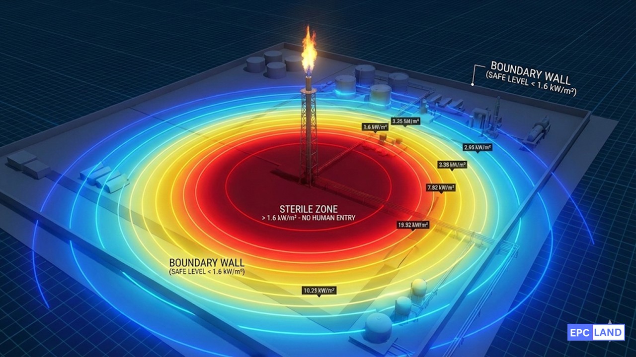
High-Hazard Zones: Flares and LPG
Flare Stack Sterile Zones
The flare is a continuous source of ignition. OISD mandates a strict flare stack sterile zone radius (exclusion zone) around the stack base.
LPG Storage Layout
Due to the risk of BLEVE (Boiling Liquid Expanding Vapor Explosion), traditional spheres require massive separation distances.
OISD 118 Minimum Separation Distances (Refinery)
The table below provides a quick reference for the minimum inter-distances required for OISD 118 Refinery Layout Compliance. Note that “Process Units” generally require the largest buffers.
| From / To | Process Unit (Hazardous) | Process Control Room | Storage Tank (Class A) | Boundary Wall |
|---|---|---|---|---|
| Process Unit | 30 meters | 30 meters (if Blast Resistant) | 30 meters | 60 meters |
| Storage Tank (Class A) | 30 meters | 15 meters | 0.5 D / 1.0 D | 20/30 meters |
| Fire Station | 60 meters | No Requirement | 60 meters | – |
| Flare Stack | 90 meters | 90 meters | 90 meters | 60 meters (Sterile Zone) |
*Values are indicative based on OISD-STD-118 (Refinery Section). Distances must be measured from battery limit to battery limit or shell to shell.
Process Safety Report
Case Study: Flare Siting & Radiation Compliance
Facility Profile
- Asset: 15 MMTPA Coastal Refinery (India)
- Project: Expansion of Petrochemical Block
- Equipment: New Elevated Flare Stack
- Constraint: Proximity to Boundary Wall
Safety Parameters
- Max Radiation (Sterile): 6.3 kW/m² (Equipment)
- Max Radiation (Boundary): 1.6 kW/m² (Public)
- Standard: OISD-STD-118 / API 521
The Challenge: The 1.6 kW/m² Limit
During a major brownfield expansion, a refinery needed to install a new flare stack to handle the emergency load from a new Dual Feed Cracker Unit. The initial plot plan placed the flare stack 60 meters from the facility’s western boundary wall.
While this met the basic dimensional guidelines of OISD 118 Refinery Layout Compliance, the QRA (Quantitative Risk Assessment) simulation revealed a critical failure. Under “Emergency Flaring” conditions (full relief load), the thermal radiation intensity at the boundary wall was calculated to be 2.5 kW/m². This violated OISD norms, which strictly cap radiation at the property line to 1.6 kW/m² (the limit for human exposure without protective gear).
Environmental Conflict
Moving the flare inward was difficult due to existing process blocks. Moving it outward impinged on the refinery green belt requirements. OISD mandates a thick plantation buffer to absorb noise and minor vapors. Reducing this green belt to accommodate the “Sterile Zone” would violate Environmental Clearance (EC) conditions.
The Engineering Solution
The engineering team had to optimize the physics rather than the geography.
- Option A (Rejected): Increasing stack height from 80m to 120m. (Rejected due to structural wind load concerns in a cyclone zone).
- Option B (Selected): Switching to a Ground Flare (Enclosed) system for normal operations + High Pressure Sonic Tip for emergency.
By utilizing a Sonic Tip design, the flame became shorter and stiffer (less tilt). This tightened the radiation contours, pulling the 1.6 kW/m² isopleth back within the boundary wall, ensuring public safety without cutting into the green belt.
Impact on Fire Systems
The layout change triggered a revision in the fire water demand calculation. OISD 118 requires specific protection for the flare knockout drum area. Since the new Ground Flare system had a larger footprint than a simple vertical stack, the deluge requirement increased. The team verified that the main fire water ring main had sufficient residual pressure to handle this new 2,500 GPM demand while maintaining the required pressure at the furthest process unit.
Result: The revised siting achieved full PESO approval, balancing the rigid constraints of process safety (Radiation) with environmental compliance (Green Belt).
EPCLand YouTube Channel
2,500+ Videos • Daily Updates
Frequently Asked Questions: Refinery Siting Criteria
Why are process unit inter-distance norms fixed at 30 meters?
The 30-meter rule in process unit inter-distance norms is derived from fire dynamics. It allows sufficient space for a fire tender to maneuver and deploy water curtains. It also ensures that the thermal radiation from a pool fire in one block does not immediately compromise the structural integrity of equipment in the adjacent block, acting as a crucial “fire break.”
When is a blast resistant control room OISD compliant?
A blast resistant control room OISD compliant design is required when the building is located within a zone where the calculated blast overpressure from a Vapor Cloud Explosion (VCE) exceeds 1 psi (approx). If a QRA study shows potential overpressure, the control room must be hardened to ensure operators survive and can safely shut down the plant during a disaster.
How is the flare stack sterile zone radius calculated?
The flare stack sterile zone radius is not a fixed number; it is a calculated exclusion zone based on thermal radiation. The zone extends to where the radiation intensity drops to 6.3 kW/m² (for sterile area) and 1.6 kW/m² (for unrestricted boundary access). Typically, this results in a radius of 60m to 90m for elevated refinery flares.
Why is LPG mounded storage spacing preferred over spheres?
Conventional spheres (Horton Spheres) require massive separation distances due to the risk of BLEVE. LPG mounded storage spacing rules are far more lenient (e.g., 15 meters) because the vessel is buried under earth, virtually eliminating the risk of external fire impingement causing an explosion. This saves valuable plot space in congested refineries.

Related posts:
![High-grade industrial Wing Nut Types and Applications for mechanical assemblies.]()
Wing Nut Types and Applications: The 2026 Engineering Guide
![Industrial Monorail Crane Systems installed in a modern manufacturing plant 2026.]()
Monorail Crane Systems: Design, Types & 2026 Standards Guide
![Lead engineer performing a Factory Acceptance Test FAT on an industrial skid system 2026]()
Factory Acceptance Test FAT: The 2026 Engineering Guide to Zero-Defect Delivery
![Professional engineering workspace showing a Basis of Design document layout for a 2026 project.]()
Basis of Design: How to Write a BOD for Engineering Projects in 2026
![Industrial Flare Knockout Drum Sizing and installation in a refinery relief system.]()
Flare Knockout Drum Sizing: Design & API 521 Standards (2026 Guide)
![Advanced Reboiler Control Systems in a modern petrochemical refinery 2026.]()
Reboiler Control Systems: Engineering Guide to Precision Control 2026


