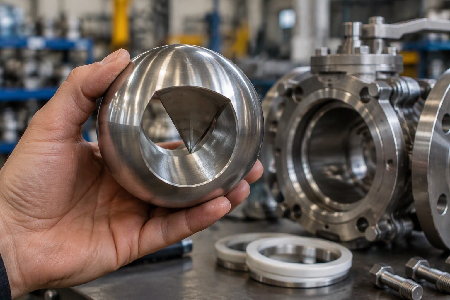
Choke Valve Trim Selection and Pressure Letdown on Christmas Tree Assemblies
In my twenty years managing high-pressure upstream production facilities, selecting the correct choke valve trim remains one of the most critical decisions for asset integrity. When an oilfield wellhead christmas tree assembly operates outdoors, external weather extremes combine with aggressive multi-phase flow conditions, creating severe operational challenges. The adjustable choke valve, equipped with a precise handwheel and position indicator, serves as the primary pressure letdown boundary between the subsurface reservoir and surface flowlines.
Engineers must carefully evaluate pressure drop ratios, fluid velocities, and sand production rates before specifying trim geometries. A mismatch in trim selection leads to catastrophic body erosion, vibration-induced fatigue, and sudden loss of containment. My objective here is to break down the exact engineering mechanics, material selections, and standard compliance frameworks necessary to master choke valve applications on production christmas trees.
Key Engineering Takeaways
- Mastering pressure letdown mechanics across multi-stage orifice geometries to prevent cavitation and fluid flash.
- Applying API 6A material classes (EE, FF, HH) and temperature ratings for sour and high-pressure service.
- Differentiating between plug-and-cage and multiple-step disc trims to mitigate high-velocity impingement wear.
- Ensuring accurate handwheel and linear position indicator calibration for reliable flow tuning in the field.
Choke Valve Trim Engineering and Pressure Letdown Mechanics
The fundamental purpose of an oilfield choke valve on a christmas tree is to drop high wellhead pressure down to surface facility operating pressure. This pressure drop induces severe fluid acceleration. When a liquid-dominated stream contains dissolved gases, rapid pressure reduction below the bubble point triggers flashing or cavitation. In my field audits, I frequently observe severe metal loss downstream of poorly selected trims due to micro-jetting and vapor bubble collapse.
To combat these destructive phenomena, modern choke valve trims use specialized flow-turning and multi-stage pressure reduction paths. Instead of taking a single pressure drop across a sharp-edged orifice, multi-step plug-and-cage designs divide the total differential pressure into incremental steps. This keeps fluid velocity below the critical erosion threshold, protecting the valve body and downstream piping elbows from premature failure.
Plug-and-Cage Versus Needle Trim Geometries
Selecting the correct internal architecture dictates the turndown ratio and control linearity of the wellhead assembly. Needle and seat trims provide simple mechanical throttling but suffer from high flow turbulence and rapid wear at small openings. Conversely, cage-guided trims feature precision-machined flow ports that direct fluid jets inward toward the center of the cage bore, preventing direct impingement on the internal body walls.
When dealing with sand-laden production streams, tungsten carbide is the industry-standard material for trim components. Tungsten carbide boasts an exceptional Vickers hardness rating, typically exceeding 1500 HV, which resists abrasive cutting. However, brittle ceramic and carbide trims require careful mechanical decoupling from the outer body to prevent cracking under thermal shock and severe mechanical vibration from high-velocity slug flow.
Engineering Warning: Critical Velocity and Erosive Wear
Exceeding the maximum erosive velocity limit (nu_max) calculated via the Stockburger equation will destroy internal trim surfaces within weeks of production start-up. Always calculate the mixture density (rho_mix) and ensure fluid velocity remains below recommended API RP 14E erosion velocity thresholds, particularly when sand production is anticipated.
API 6A Compliance and Material Selection Requirements
Wellhead christmas tree components operate under stringent regulatory frameworks. API Specification 6A governs the material requirements, welding qualifications, and pressure containment standards for all valves and chokes. Material classes range from AA through HH, dictating carbon steel, alloy steel, or corrosion-resistant alloy (CRA) requirements based on partial pressures of carbon dioxide and hydrogen sulfide.
For sour service environments containing high concentrations of H2S, internal trim components must comply with NACE MR0175 / ISO 15156 hardness limits. Hardness exceeding HRC 22 in carbon and low-alloy steels promotes sulfide stress cracking. Therefore, overlay welding with Stellite or solid tungsten carbide inserts is mandatory for structural longevity in aggressive sweet and sour production wells.
Actuation, Handwheels, and Position Indicators
Manual adjustable chokes rely on a robust external handwheel connected to a non-rising or rising stem that adjusts the relative position of the plug within the seat or cage. An accurate mechanical or digital position indicator is essential for operators to translate handwheel turns into precise flow area increments, typically measured in 64ths of an inch (bean size equivalents).
In remote or high-pressure locations, manual positioning gives way to stepping electric or pneumatic actuators tied to supervisory control systems. Regardless of actuation type, backlash in the stem threads must be minimized to ensure the position indicator accurately reflects the true effective flow port area during delicate well-testing and production-choking operations.
Engineering Advantages
- Precise flow tuning via multi-turn handwheels and clear linear position indicators.
- Exceptional erosion resistance when using solid tungsten carbide or ceramic trim components.
- Full compliance with API 6A material classes for high-pressure sour and sweet service.
- Effective pressure letdown attenuation preventing downstream pipeline vibration and fatigue.
- Modular trim replacement allowing in-line maintenance without removing the entire valve body.
Engineering Disadvantages
- High initial capital cost for specialized tungsten carbide and corrosion-resistant alloy trims.
- Susceptibility to severe mechanical jamming if formation sand accumulates in tight clearances.
- Vulnerability to thermal shock cracking under rapid well startup or cryogenic gas expansion.
- Complex maintenance procedures requiring certified technicians for internal trim extraction.
- Potential for flow cavitation and noise generation if pressure drop ratios exceed critical limits.
High-Pressure Gas Well Production
Gas-condensate wells operating above 10,000 psi require multi-stage choke trims to manage extreme pressure drops. The multi-step design prevents supersonic gas velocities that cause severe body erosion and acoustic fatigue in surface production manifolds.
Sand-Producing Unconventional Oil Wells
Tight oil reservoirs producing abrasive proppant and formation sand rely on solid tungsten carbide cage trims. This architecture withstands particle impact by directing flow inward, shielding the outer valve body from abrasive cutting during peak drawdown.
Offshore Platform Christmas Trees
Topside christmas tree assemblies on offshore platforms demand compact, highly reliable adjustable chokes with precise position indicators. Operators use these manual or hydraulic chokes to balance individual well contributions into common production headers.
Sour Service High-H2S Fields
Fields with elevated hydrogen sulfide concentrations require API 6A Material Class EE or FF chokes. Specially hardened nickel-alloy trims prevent sulfide stress cracking while maintaining precise flow control under aggressive chemical injection regimens.
Thermal Recovery and Steam Injection Wells
Enhanced oil recovery projects utilizing cyclic steam stimulation utilize specialized high-temperature trims. These components accommodate extreme thermal expansion cycles without binding or losing positional calibration on the handwheel indicator.
Choke Valve Trim Design and Material Specifications
Selecting the correct choke valve trim material and geometry is critical for managing severe fluid velocities, high-pressure drops, and abrasive solid particles common in upstream oil and gas production. In my experience operating high-pressure Christmas tree assemblies, mismatched trim components lead to premature erosion, catastrophic pressure boundary failures, and costly downtime. The data table below outlines standard material classifications, operational pressure limits, and recommended trim types according to API Specification 6A and NACE MR0175 sour service guidelines.
Engineers must cross-reference these material groups against the specific wellbore fluid composition, evaluating the partial pressures of hydrogen sulfide and carbon dioxide alongside sand production rates before finalizing the bill of materials.
| Trim Designation | Base Material & Hardfacing | Max Working Pressure | Primary Service Environment | Applicable Standard |
|---|---|---|---|---|
| T-20 (Basic) | 316 Stainless Steel with Stellite Hardfacing | 5,000 PSI (34.5 MPa) | Sweet gas and light crude with minimal sand | API 6A / ASTM A182 |
| T-30 (Abrasive) | Tungsten Carbide Solid Sleeves & Cages | 10,000 PSI (68.9 MPa) | High sand cut production and multiphase flow | API 6A Annex F |
| T-50 (Sour) | Inconel 718 Core with Ceramic Trim Elements | 15,000 PSI (103.4 MPa) | High H2S, CO2, and severe chloride scaling | NACE MR0175 / ISO 15156 |
| T-70 (Extreme) | Zirconia Toughened Alumina Ceramic Trim | 20,000 PSI (137.9 MPa) | Ultra-high pressure high-temperature HPHT wells | API 6A PR2 Qualified |
Note: All high-pressure trims undergo rigorous gas testing and cyclic endurance verification prior to Christmas tree integration.
Technical Mapping & Specifications Matrix
To ensure seamless integration within complex production manifolds, engineers rely on standardized technical entity mapping. This matrix details the vital structural acronyms, physical parameters, and governing compliance standards that dictate wellhead choke valve design. Every parameter listed below directly influences the pressure letdown calculation and ensures structural integrity under extreme thermal and mechanical loading.
Reviewing these parameters during the front-end engineering design phase prevents costly field retrofits and guarantees full regulatory compliance across international jurisdictions.
| Technical Entity | Structural Acronym | Primary Physical Parameter | Governing Compliance Standard |
|---|---|---|---|
| Valve Flow Coefficient | Cv / Kv | Volumetric flow rate of water at 60 Fahrenheit through fully open valve at 1 PSI differential | IEC 60534 |
| Pressure Drop Ratio | Delta-P / P1 | Ratio of pressure drop across trim to upstream absolute pressure | API 6A |
| Material Class | MC (EE, FF, HH) | Metallurgical resistance rating against sour gas and chloride stress corrosion | NACE MR0175 |
| Performance Requirement | PR1 / PR2 | Thermal cycling and high-pressure operational validation test cycles | API 6A Annex F |
Entity verification ensures complete traceability from raw billet forging to final factory acceptance testing.
Field Verification Checklist for Choke Valve Assembly
Choke valve installation and pre-commissioning require rigorous adherence to quality control protocols. Before energizing any oilfield Christmas tree assembly, field engineers must systematically verify mechanical alignment, handwheel responsiveness, position indicator calibration, and pressure boundary integrity. Skipping verification steps frequently leads to operational failure, stem binding, or uncontrolled well flow during initial startup.
The structured verification workflow below outlines the essential milestones required for safe, compliant, and reliable choke valve operation in harsh outdoor production environments.
Pre-Commissioning & Installation Inspection Steps
- Visual Body Inspection: Inspect the choke valve body exterior for shipping damage, coating holidays, and ensure all flange bolting conforms to ASME B16.5 torque specifications.
- Handwheel Calibration: Verify that the manual handwheel rotates smoothly from fully closed (0 percent) to fully open (100 percent) without binding or excessive backlash.
- Position Indicator Alignment: Confirm that the mechanical position indicator accurately reflects the internal stem travel and orifice opening percentage relative to flow calibration charts.
- Hydrostatic Pressure Testing: Perform a body hydrostatic test at 1.5 times the rated working pressure in accordance with API 6A guidelines.
- Sour Service Verification: Cross-check material test reports against NACE MR0175 hardness limits (maximum 22 HRC for low alloy steel components).
- Downstream Piping Support: Ensure proper pipe supports and expansion loops are installed downstream of the choke to absorb vibration induced by high-velocity pressure letdown.
Completion of all checklist items must be signed off by a certified quality control inspector before handing over the wellhead assembly to production operations.
Field Case Study: Real-World Application
Examining real-world operational failures provides invaluable insight into choke valve selection and pressure letdown management. Below is an engineering analysis of a severe failure encountered on an offshore-adjacent onshore production cluster, highlighting the root cause and the permanent engineering resolution implemented.
Operational Problem Analysis
A high-pressure gas-condensate well experienced severe vibration and premature body washout within three weeks of initial production startup.
- Incorrect trim selection utilizing standard 316 stainless steel instead of tungsten carbide cages.
- Excessive pressure drop ratio exceeding 0.85 across a single-stage choke, inducing sonic flow and localized cavitation.
- Sand production from unconsolidated formations acting as an abrasive slurry against internal stem components.
- Misalignment of the mechanical position indicator leading to operator error and uncontrolled flow surges.
Engineering Resolution & Outcome
Replacing the conventional trim with an API 6A compliant multi-stage tungsten carbide cage system eliminated vibration and extended service life beyond three years.
- Achieved stable pressure letdown across three discrete expansion stages, preventing localized fluid flashing and erosion.
- Upgraded material metallurgy to meet NACE MR0175 sour service standards for enhanced structural integrity.
- Installed a calibrated linear position indicator with feedback loop to the SCADA control room.
- Eliminated unplanned downtime, saving an estimated 450,000 dollars in deferred production losses.
Recommendation: Always perform multiphase flow modeling and sand erosion analysis during the Front-End Engineering Design phase to select appropriate choke trims before Christmas tree fabrication.
Frequently Asked Engineering Questions
What is the primary function of a choke valve trim in a Christmas tree assembly?
The primary function of a choke valve trim is to safely dissipate high wellhead pressure while precisely regulating production flow rates according to reservoir management guidelines.
- Converts high-pressure potential energy into controlled kinetic turbulence.
- Protects downstream flowlines and processing equipment from erosion and pressure spikes.
- Maintains backpressure on the reservoir to prevent sand production and formation collapse.
- Complies strictly with API 6A specifications for wellhead equipment integrity.
When should an engineer specify a positive choke versus an adjustable choke?
Selection between positive and adjustable chokes depends on fluid abrasiveness, operational frequency, and the need for continuous versus stepped flow tuning.
- Use positive chokes with bean inserts for severely sandy wells where erosion rates destroy adjustable internal stems quickly.
- Use adjustable chokes featuring handwheels for test wells or installations requiring frequent flow rate adjustments without bean swaps.
- Ensure selected bodies meet material class and temperature rating requirements outlined in ISO 10423 standards.
How does cavitation impact choke valve trim life in high-pressure letdown service?
Cavitation generates violent vapor bubble collapses near solid metal surfaces, causing severe localized pitting, noise, and rapid destruction of standard trim materials.
- Occurs when fluid pressure drops below vapor pressure through the restriction and recovers downstream.
- Mitigate damage by utilizing multi-stage pressure letdown trim or tungsten carbide components.
- Verify that pressure drops stay within safe limits defined by ASME B31.3 piping guidelines.
What material grades are required for choke trims in sour service environments?
Sour service environments containing hydrogen sulfide require specialized metallurgy to prevent catastrophic sulfide stress cracking under high operating stresses.
- Comply strictly with material manufacturing rules and hardness limits specified in NACE MR0175 / ISO 15156.
- Specify solid tungsten carbide or nickel-alloy overlays for internal stems and seats.
- Ensure body material classes meet API 6A requirements for material classes DD through FF.
Why is a visual position indicator critical on manual adjustable choke valves?
A clear position indicator provides operators with immediate visual confirmation of stem travel and relative opening percentage during manual flow tuning.
- Eliminates guesswork when operators make incremental adjustments using the handwheel.
- Facilitates accurate logging of choke turns and fractional openings during well testing routines.
- Supports safety verification walks by confirming valve position matches supervisory control data.
Field Recommendation
-
1
Specify Tungsten Carbide Trims for Sandy Service: If well fluid analysis indicates sand production exceeding 50 ppm, choose solid tungsten carbide needle and seat trims over standard stainless steel variants because erosive velocity wear will otherwise destroy internal pressure boundaries within weeks of initial startup.
-
2
Mandate API 6A PR2 Validation: When designing high-pressure surface Christmas tree assemblies operating above 10,000 psi, specify that all adjustable choke valves must carry documented PR2 prototype test validation to guarantee seal reliability under extreme thermal cycling and dynamic stem movement.
-
3
Enforce NACE MR0175 Compliance: If trace hydrogen sulfide is detected in gas samples, choose alloy body materials and trim overlays meeting NACE MR0175 hardness thresholds because standard carbon steel components risk sudden sulfide stress cracking failure under high differential pressures.
-
4
Implement Staged Pressure Letdown: When pressure drop ratios exceed critical cavitation limits across a single restriction, choose multi-stage trim configurations or external bean staging because single-stage high-velocity flashing will rapidly erode downstream piping elbows and weld joints.
Complete Course on
Piping Engineering
Check Now
Key Features
- 125+ Hours Content
- 500+ Recorded Lectures
- 20+ Years Exp.
- Lifetime Access
Coverage
- Codes & Standards
- Layouts & Design
- Material Eng.
- Stress Analysis
