Understanding LO and LC in Valves: The Definitive Engineering Guide
The LO and LC in Valves notations are fundamental safety requirements in process piping, ensuring that critical isolation points remain in their fail-safe or operational positions during hazardous procedures.
Quick Definition: LO vs LC
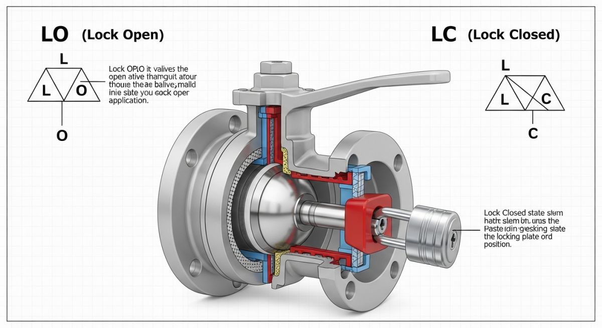
In engineering, LO and LC in Valves stand for Locked Open and Locked Closed. A Locked Open (LO) valve is secured in the open position to maintain continuous flow (e.g., relief paths), while a Locked Closed (LC) valve is secured shut to prevent accidental intake or discharge of hazardous fluids.
Table of Contents
- 1. What is the Meaning of LO and LC in Valves?
- 2. Engineering Specifications for Locked Open (LO) Valves
- 3. Safety Protocols for Locked Closed (LC) Valves
- 4. Valve Locking Device Standards
- 5. Difference Between Car Seal Open (CSO) and LO/LC
- 6. ASME B31.3 Safety Valves Requirements
- 7. LO and LC in Valves Torque Calculator
Process Safety Quiz: Valve Control Notations
Question 1/5Quiz Completed!
Complete Course on
Piping Engineering
Check Now
Key Features
- 125+ Hours Content
- 500+ Recorded Lectures
- 20+ Years Exp.
- Lifetime Access
Coverage
- Codes & Standards
- Layouts & Design
- Material Eng.
- Stress Analysis
What is the Meaning of LO and LC in Valves? (Operational Overview)
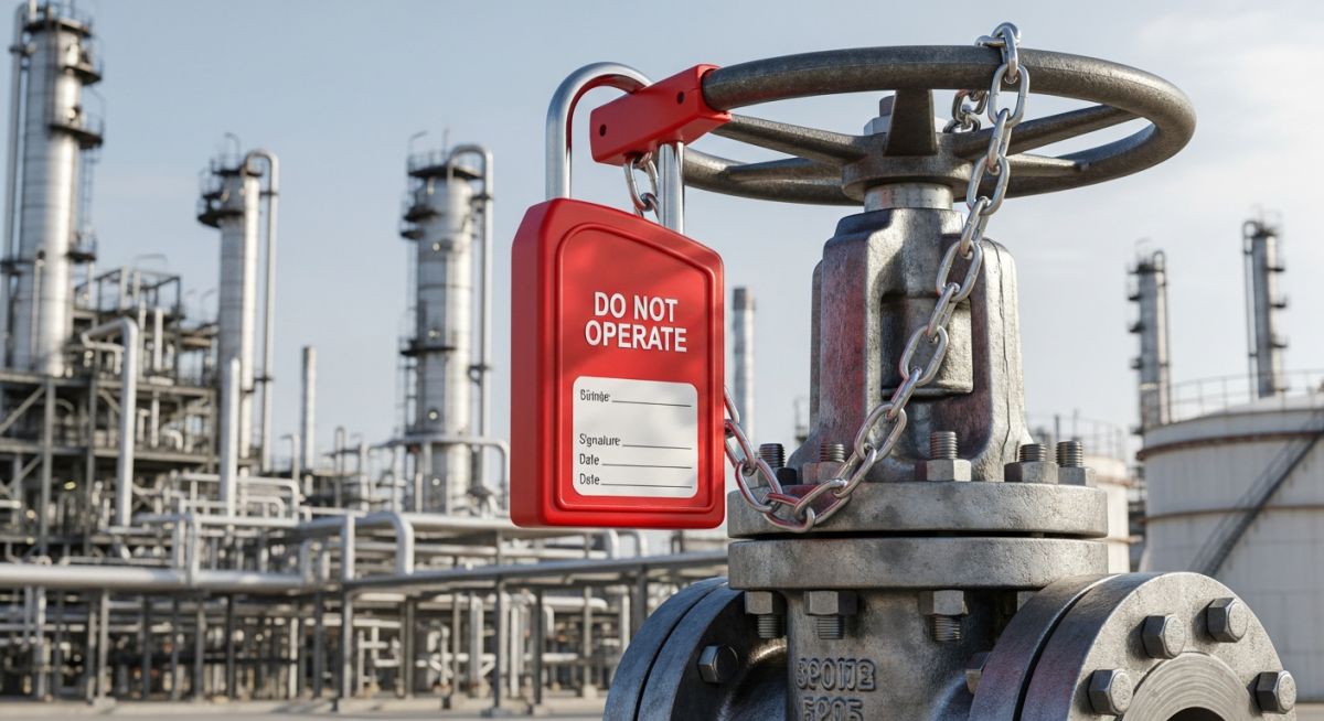
In the context of 2026 process safety management, the Meaning of LO and LC in Valves refers to the administrative and physical control of manual valves. These notations are not merely suggestions; they are critical safety requirements dictated by Piping and Instrumentation Diagrams (P&IDs). A valve designated as LO (Locked Open) or LC (Locked Closed) requires a physical locking device—typically a padlock or heavy-duty chain—to prevent unauthorized or accidental operation that could lead to catastrophic equipment failure or personnel injury.
Unlike standard NO (Normally Open) or NC (Normally Closed) valves, which are expected to be in a certain state but are not physically restricted, LO and LC in Valves must be managed through a Master Key Register. This ensures that only authorized personnel can change the state of the valve, usually under a strictly controlled Work Permit System.
Engineering Specifications for Locked Open (LO) Valves
A Locked Open (LO) Valves specification is most commonly found on safety-critical flow paths. The primary engineering goal is to ensure that a relief or bypass route is never inadvertently blocked. If an LO valve is accidentally closed, it can cause upstream pressure to exceed the Maximum Allowable Working Pressure (MAWP) of the vessel, leading to a loss of containment.
Critical Applications for LO Notations in P&IDs
According to 2026 refinery standards, LO status is mandatory for:
- PSV Inlet/Outlet: Block valves located before or after a Pressure Safety Valve.
- Flare Headers: Main isolation valves connecting process units to the flare system.
- Cooling Water: Critical supply lines for exothermic reactors where cooling loss would cause a runaway reaction.
- Instrument Air: Main supply lines to fail-safe pneumatic controllers.
Safety Protocols for Locked Closed (LC) Valves
Conversely, Locked Closed (LC) Valves are essential for isolating hazardous energy or preventing the mixing of incompatible fluids. In 2026, LC protocols are a cornerstone of Double Block and Bleed (DBB) systems, providing a physical guarantee that a closed path remains closed.
Preventing Accidental Overpressurization with LC Controls
The use of LO and LC in Valves for isolation prevents "human error" scenarios where a bypass valve might be opened under pressure. For example, a high-pressure nitrogen purge line must be LC when not in use to prevent high-pressure gas from entering a low-pressure process vessel, which could cause a catastrophic rupture.
| Notation | Operational State | Primary Risk |
|---|---|---|
| LO | Locked Open | Blockage of relief path / Overpressure |
| LC | Locked Closed | Contamination / Unintended pressurization |
Mechanical Locking Devices and Valve Locking Device Standards
Modern 2026 engineering frameworks, including ISO 28621, define the hardware requirements for maintaining the integrity of LO and LC in Valves. A locking device is not merely a padlock; it is a system designed to resist environmental corrosion and unauthorized tampering. In high-vibration environments, locking plates must be used to ensure the valve handle cannot be moved even if the lock is engaged.
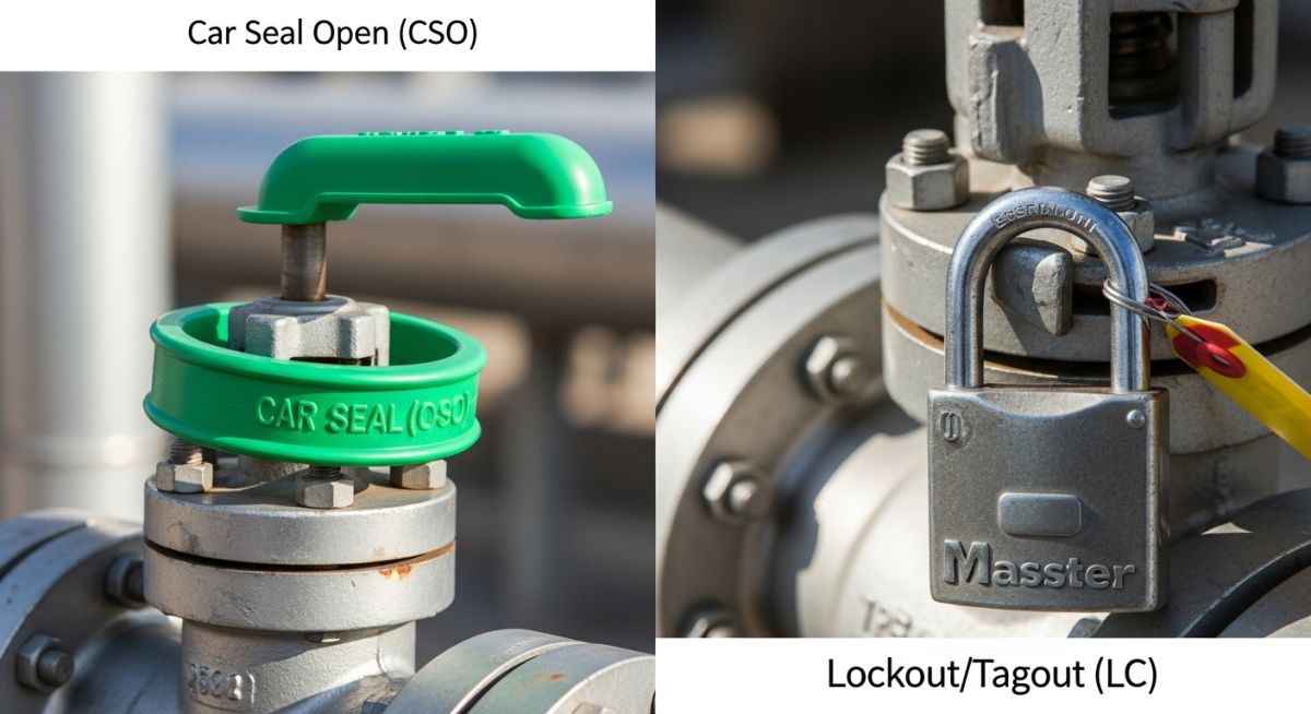
Difference Between Car Seal Open (CSO) and LO and LC in Valves
A common point of confusion in plant operations is the distinction between a car seal and a physical lock. While both serve the goal of status verification, their administrative weight differs significantly:
| Feature | LO and LC (Locked) | CSO and CSC (Car Seal) |
|---|---|---|
| Security Level | High (Physical padlock and key) | Medium (Breakable plastic/wire seal) |
| Key Control | Requires Master Key Register | No key; seal is cut to operate |
| Verification | Administrative log check | Visual inspection of seal integrity |
| 2026 Use Case | Safety Instrumented Systems (SIS) | Utility and Non-critical process lines |
ASME B31.3 Safety Valves Requirements for Locked Manifolds
The ASME B31.3 Safety Valves guidelines specify that any valve located in a pressure-relieving path must be either LO or provided with an interlock. For multi-relief systems where one PSV is online and one is standby, the selector valves must be synchronized: one LO and one LC.
Engineering Calculation: Locking Chain Strength
To ensure the mechanical integrity of LO and LC in Valves, the chain must withstand the maximum manual operating torque applied by a lever. The required tensile strength (Treq) is calculated as:
Treq = (Torquemax / Radiushandwheel) * Safety Factor
Note: Standard safety factors for 2026 petrochemical facilities are typically set at 2.5. If Torquemax is 150 Newton-meters and the radius is 0.2 meters, the required chain strength must exceed 1875 Newtons.
EPCLand YouTube Channel
2,500+ Videos • Daily Updates
LO and LC in Valves Torque Calculator
Calculate the minimum required tensile strength for valve locking chains based on 2026 safety standards.
Advanced Interlock Systems: A Deep Dive into Trapped Key Exchange
While LO and LC in Valves provide excellent static protection, some 2026 industrial processes require sequential control to prevent catastrophic human error. Trapped Key Interlocking (TKI) is a mechanical safety system that enforces a predefined operating sequence. In these systems, a valve can only be operated if the correct key is inserted, and that key remains "trapped" until the valve is returned to its safe LO or LC state.
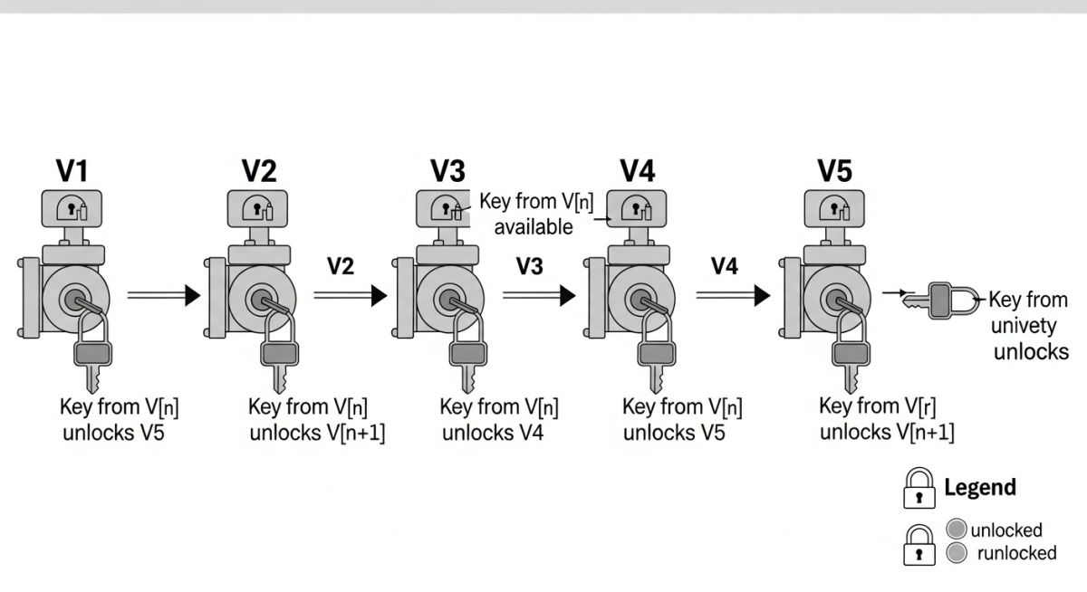

The Principle of Key Transfer for LO and LC
In a typical 2026 "Key Exchange" scenario for a Pressure Safety Valve (PSV) manifold, the sequence ensures that the backup PSV is fully online before the primary PSV is isolated. The mechanical logic follows these steps:
- Step 1: Key A is released from the Control Room.
- Step 2: Key A unlocks the Standby Inlet Valve (previously LC). Once fully opened, the valve traps Key A and releases Key B.
- Step 3: Key B is taken to the Duty Inlet Valve. It unlocks the valve, allowing it to be Locked Closed (LC). Once closed, Key B is trapped and Key C is released.
- Step 4: Key C is returned to the Control Room, confirming the successful switchover without ever blocking the relief path.
Applications in Modern 2026 Facilities
Trapped key systems are now integrated with electronic "Smart Keys" that log the exact timestamp of every LO and LC in Valves transition. This provides a digital audit trail that complies with the latest OSHA and EU safety directives.
| System Type | Complexity | Best For |
|---|---|---|
| Standard LO/LC | Low | General isolation and utility lines. |
| Trapped Key Interlock | High | PSV Manifolds, Pig Launchers, and Boiler Blowdown. |
Engineering Case Study: Critical Failure of LO and LC in Valves Protocols
Project Data (2026 Audit)
- Facility Type: Hydrocarbon Processing Plant
- Component: HP/LP Interface Manifold
- System Pressure: 120 Bar (High Side) / 10 Bar (Low Side)
- Missing Notation: LC (Locked Closed) on Bypass
Failure Analysis
During a 2026 routine maintenance cycle, a manual bypass valve intended to be LC (Locked Closed) was found unsecured. An operator, misinterpreting the line status, partially opened the valve. This caused high-pressure gas to backflow into a low-pressure storage vessel, resulting in an emergency shutdown (ESD) and near-rupture.
Engineering Fix & Mitigation
The investigation led to the immediate implementation of a Master Key Register and the replacement of all standard handwheels with specialized locking caps. These caps ensure that the Meaning of LO and LC in Valves is physically enforced, making it impossible to rotate the valve stem without a unique key assigned to the Shift Supervisor.
Lessons Learned
Administrative "Normally Closed" (NC) tags are insufficient for high-risk interfaces. Critical isolation must always utilize LO and LC in Valves hardware to eliminate human error. In 2026, automated "Valve Position Monitoring" (VPM) sensors are now being integrated with LO/LC locks to provide real-time feedback to the Control Room.
Frequently Asked Questions: Valve Locking Protocols
Who is authorized to remove a lock from LO and LC in Valves?
As of 2026, only authorized personnel (typically a Shift Supervisor or Area Lead) designated in the Master Key Register may remove locks. This must be done under a specific Work Permit or Management of Change (MOC) protocol to ensure process safety is not compromised.
Can I use a plastic Car Seal for a valve designated as Locked Closed (LC)?
Generally, no. If the P&ID specifies LC (Locked Closed), a physical padlock and key are required. A plastic car seal is only acceptable if the engineering notation is CSC (Car Seal Closed), which provides visual evidence of tampering but lacks physical resistance.
What are the Valve Locking Device Standards for corrosive environments?
For 2026 offshore or chemical plant applications, stainless steel (Grade 316) chains and brass or weather-protected padlocks must be used. All locking hardware must comply with OSHA 1910.147 for energy isolation and ASME B31.3 for piping integrity.
How does LO and LC affect the P&ID development?
During the P&ID Notations phase, engineers must identify every valve that, if operated incorrectly, could cause a hazard. These are then labeled LO or LC, which triggers the procurement of physical locking hardware during the construction phase.
Final Conclusion on Valve Safety
Mastering the LO and LC in Valves protocol is a non-negotiable skill for any process engineer or plant operator in 2026. These symbols on a P&ID represent the physical barriers between safe operation and catastrophic failure. By strictly adhering to ASME B31.3 and ISO locking standards, facilities can ensure that critical flow paths remain open and hazardous isolations remain closed, protecting both the environment and human life.
Last Updated: January 2026 | Technical Audit by Epcland Dev Architect.

Related posts:
![High-grade industrial Wing Nut Types and Applications for mechanical assemblies.]()
Wing Nut Types and Applications: The 2026 Engineering Guide
![Industrial Monorail Crane Systems installed in a modern manufacturing plant 2026.]()
Monorail Crane Systems: Design, Types & 2026 Standards Guide
![Lead engineer performing a Factory Acceptance Test FAT on an industrial skid system 2026]()
Factory Acceptance Test FAT: The 2026 Engineering Guide to Zero-Defect Delivery
![Professional engineering workspace showing a Basis of Design document layout for a 2026 project.]()
Basis of Design: How to Write a BOD for Engineering Projects in 2026
![Industrial Flare Knockout Drum Sizing and installation in a refinery relief system.]()
Flare Knockout Drum Sizing: Design & API 521 Standards (2026 Guide)
![Advanced Reboiler Control Systems in a modern petrochemical refinery 2026.]()
Reboiler Control Systems: Engineering Guide to Precision Control 2026


