How Intelligent Pipeline Integrity Management Eliminates Catastrophic Failures
In my 20 plus years of managing high-pressure transmission pipelines, I have watched the industry transition from reactive “run-to-failure” mindsets to highly sophisticated proactive strategies. Historically, we relied on periodic hydrostatic testing and scheduled inline inspection (ILI) runs to tell us if a line was compromised. This approach left massive blind spots between inspection intervals. Today, the integration of artificial intelligence, edge computing, and continuous sensor networks has changed the paradigm completely.
By leveraging real-time data streams, we no longer guess when a defect will reach its critical limit. We model its growth continuously under dynamic operating conditions. This article details the engineering mechanics, mathematical formulations, and field-tested strategies required to implement a zero-failure pipeline integrity program.
Key Engineering Takeaways
- Understand how real-time transient modeling (RTTM) identifies micro-leaks within minutes instead of days.
- Master the application of modified ASME B31G and RSTRENG calculations for active defect assessment.
- Learn to integrate distributed fiber optic sensing (DAS/DTS) with predictive machine learning algorithms.
- Discover the exact verification protocols needed to audit an intelligent integrity system.
Why Intelligent Pipeline Integrity Management Prevents Disasters
Traditional pipeline integrity programs rely heavily on prescriptive intervals defined by codes like ASME B31.8S (Managing System Integrity of Gas Pipelines) and API RP 1160 (Managing System Integrity for Hazardous Liquid Pipelines). While these standards provide an excellent baseline, they are inherently static. They assume that corrosion rates and stress profiles remain constant between inspection cycles.
In reality, pipelines experience highly dynamic environments. Pressure cycling, soil stress, temperature fluctuations, and chemical variations in the product stream create non-linear degradation rates. This is where intelligent pipeline integrity management steps in. By feeding continuous SCADA data, cathodic protection (CP) telemetry, and inline inspection history into predictive algorithms, we can calculate the real-time safety factor of any given pipeline segment.
The Physics of Failure: Stress Corrosion Cracking and Localized Pitting
To prevent failures, we must mathematically model the degradation mechanisms. Let us look at localized pitting corrosion. When an inline inspection tool identifies a metal loss defect, we must calculate its safe operating pressure. The traditional ASME B31G formula defines the safe operating pressure (P_safe) as:
Where:
• d = maximum depth of the corrosion defect
• t = nominal wall thickness of the pipe
• P_design = design pressure of the pipeline
• M = Folias (bulging) factor, calculated as:
Where L is the longitudinal length of the defect and D is the nominal outer diameter of the pipe.
While ASME B31G is conservative, it often leads to unnecessary repairs on non-critical defects. Intelligent systems utilize the RSTRENG (Modified B31G) method or direct 3D Finite Element Analysis (FEA) to model the exact profile of the defect. The modified Folias factor (M) for longer defects where the parameter (L^2 / (D * t)) is greater than 50 is calculated using:
By integrating these calculations into an automated cloud-based engine, the system continuously recalculates the remaining strength of the pipe as new operational data arrives. If a pressure surge occurs, the system instantly flags defects whose safety margins have dropped below acceptable limits.
Integrating Distributed Fiber Optic Sensing (DFOS)
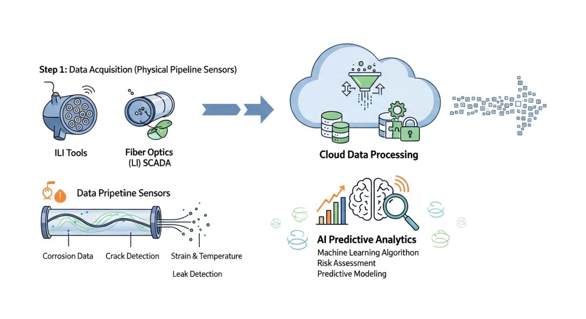
One of the most powerful tools in modern integrity management is Distributed Fiber Optic Sensing. By laying a fiber optic cable parallel to the pipeline, we can utilize Distributed Acoustic Sensing (DAS) and Distributed Temperature Sensing (DTS) to turn the entire pipeline length into a continuous sensor.
DAS works by sending laser pulses down the fiber and measuring the backscattered light. Any acoustic vibration near the pipeline—such as a micro-leak, third-party excavation, or ground movement—alters the backscatter pattern. Machine learning models trained on acoustic signatures can instantly differentiate between a passing agricultural tractor and an illegal hot-tap attempt, alerting operators before physical damage occurs.
The table below outlines the critical differences between traditional assessment methods and intelligent, real-time calculations when evaluating pipeline metal loss defects.
| Assessment Parameter | ASME B31G (Traditional) | RSTRENG (Modified) | Intelligent Real-Time FEA |
|---|---|---|---|
| Defect Geometry Profile | Simplified parabolic or parabolic-arc approximation. | Detailed “effective area” profile using actual pit depths. | Full 3D laser scan or high-resolution ILI point-cloud mapping. |
| Flow Stress Definition | 1.1 * SMYS (Specified Minimum Yield Strength) | SMYS + 10,000 psi (68.9 MPa) | Actual material tensile properties derived from mill test reports. |
| Conservatism Level | Very High (Often leads to premature repairs) | Moderate (Industry standard for safe optimization) | Optimized (Calculates exact safety margins dynamically) |
| Data Input Frequency | Static (Updated only during ILI runs every 3-7 years) | Static (Calculated manually post-inspection) | Continuous (Updated via live SCADA pressure telemetry) |
This matrix maps physical pipeline parameters to their corresponding digital twin monitoring technologies and regulatory standard references.
| Physical Parameter | Sensor Technology | AI/ML Model Applied | Standard Reference |
|---|---|---|---|
| Wall Thinning & Pitting | Magnetic Flux Leakage (MFL) & Ultrasonic Testing (UT) ILI Tools | Random Forest & Neural Networks for Corrosion Growth Rate (CGR) forecasting | ASME B31G / RSTRENG |
| Transient Pressure Waves | High-speed dynamic pressure transmitters | Real-Time Transient Modeling (RTTM) for leak localization | API RP 1130 |
| Ground Movement & Strain | Distributed Acoustic Sensing (DAS) & Inertial Measurement Units (IMU) | Pattern recognition algorithms for geohazard detection | ASME B31.8 Appendix N |
| Cathodic Protection Levels | Wireless CP rectifiers & remote monitoring units (RMU) | Anomaly detection models for localized coating holiday identification | NACE SP0169 / ISO 15589-1 |
How to Audit Intelligent Pipeline Integrity Management Systems
Deploying an intelligent integrity platform is only half the battle. As a lead engineer, you must perform regular audits to ensure the digital twin matches physical reality. Sensor drift, communication dropouts, and algorithmic bias can lead to catastrophic false negatives. Use the checklist below during your quarterly system audits.
Field Audit & Validation Steps
-
Verify Telemetry Calibration: Cross-reference physical pressure gauge readings at block valve stations with the SCADA HMI values. Discrepancies must be under 0.05% of the full-scale sensor range.
-
Validate Corrosion Growth Models: Compare the predicted corrosion depth from your machine learning model against actual physical measurements taken during excavation and direct assessment (NACE SP0502).
-
Test Leak Detection Latency: Conduct a controlled fluid withdrawal test (where permitted) or simulate a transient pressure wave to verify that the RTTM system triggers an alarm within the time limits specified by API RP 1130.
-
Audit Fiber Optic Sensitivity: Perform a physical ground-tap test near the buried fiber optic cable to confirm that the DAS system correctly classifies and localizes the acoustic disturbance within plus or minus 10 meters.
-
Review Data Ingestion Latency: Ensure that the end-to-end data latency from edge sensors to the cloud-based predictive engine does not exceed 5 seconds to maintain real-time transient modeling accuracy.
Field Case Study: Real-World Application
The Problem: Undetected Stress Corrosion Cracking (SCC)
A 24-inch crude oil transmission pipeline operating at 72% SMYS crossed a geohazard zone prone to slow-moving landslips. Traditional inline inspection runs were scheduled on a 5-year cycle. During year 3, localized soil movement induced high bending stresses on a pipe segment, accelerating Stress Corrosion Cracking (SCC). The existing static integrity model did not account for this localized strain increase, leaving the operator unaware of a rapidly growing crack that had reached 65% of the wall thickness.
The Outcome: Real-Time Detection and Mitigation
The operator deployed an intelligent pipeline integrity management system integrating strain gauges, satellite-based InSAR ground movement monitoring, and a predictive digital twin. Within 48 hours of a minor soil shift, the system flagged a localized strain spike exceeding 0.2%. The predictive engine recalculated the remaining life of the segment, showing that the critical crack size would be reached within 30 days.
An emergency excavation was ordered. Field technicians confirmed the presence of the crack exactly where the system predicted. The line was safely depressurized, repaired with a composite sleeve, and returned to service without a single drop of product spilled, saving an estimated 12 million in environmental cleanup and regulatory fines.
My Recommendation: Do not treat geohazard monitoring as a separate discipline. Integrate your geotechnical sensors directly into your primary pipeline integrity digital twin to allow real-time stress recalculations.
Answering Questions on Intelligent Pipeline Integrity Management
How does machine learning improve on traditional corrosion growth rate calculations?
What is the role of API RP 1130 in intelligent leak detection?
Can fiber optic sensing replace traditional inline inspections?
How do you handle false alarms in AI-driven leak detection systems?
What is the impact of hydrogen blending on pipeline integrity management?
How does ASME B31.8S guide the development of digital twins?
===
Complete Course on
Piping Engineering
Check Now
Key Features
- 125+ Hours Content
- 500+ Recorded Lectures
- 20+ Years Exp.
- Lifetime Access
Coverage
- Codes & Standards
- Layouts & Design
- Material Eng.
- Stress Analysis