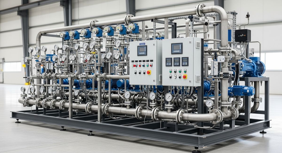
What is an Industrial Pump Skid and Its Key Advantages?
In my 20 years of designing process plants, I have seen field construction timelines completely derailed by piping misalignment, welding delays, and instrumentation calibration issues. That is why the industry has shifted heavily toward modularization. When you specify a pre-engineered system, you are not just buying hardware; you are buying guaranteed performance, factory-tested integrity, and a massive reduction in field labor hours. Let me walk you through the engineering realities of these systems.
Key Engineering Takeaways
- Drastic Schedule Compression: Parallel path construction allows site civil work and skid fabrication to occur simultaneously.
- Single-Source Accountability: One engineering firm owns the process guarantee, mechanical alignment, and electrical loop checks.
- Superior Quality Control: Shop welding, non-destructive examination (NDE), and hydrostatic testing are performed under controlled factory conditions.
- Minimized Footprint: 3D CAD modeling optimizes spatial layout, reducing the physical footprint by up to 40% compared to field-built systems.
Why Choose an Industrial Pump Skid Package?
When designing an industrial pump skid, the engineering team must balance hydraulic performance, structural rigidity, and maintenance accessibility. In my experience, the mechanical design of the structural steel baseplate is just as critical as the pump selection itself. If the baseplate flexes during transport or operation, it introduces severe shaft misalignment, leading to premature bearing failure and mechanical seal leaks.
Hydraulic Calculations & NPSH Margin
A primary advantage of shop-fabricated skids is the ability to precisely control the suction piping geometry. To prevent cavitation, the Net Positive Suction Head Available (NPSHa) must exceed the Net Positive Suction Head Required (NPSHr) by a safe margin. We calculate NPSHa using the following standard formula:
Where:
Hp = Absolute pressure on the surface of the liquid in the suction vessel (expressed in feet or meters of head).
Hz = Static elevation head of the liquid level above or below the pump centerline (positive for flooded suction, negative for suction lift).
Hf = Friction losses in the suction piping, valves, and fittings.
Hvp = Vapor pressure of the liquid at the operating temperature.
In a modular design, we minimize Hf by utilizing long-radius elbows, full-port isolation valves, and straight pipe runs directly preceding the pump suction nozzle (typically a minimum of 5 to 10 times the pipe diameter, in accordance with HI 9.6.6 standards).
Never assume a factory-aligned pump skid remains aligned after transport. Road transport introduces significant dynamic forces that can warp structural steel frames. Always perform a final shaft alignment check using laser alignment tools after the skid is anchored and grouted to its concrete foundation, prior to connecting external field piping.
Structural Rigidity and Vibration Mitigation
The structural frame must be designed to withstand both static operating loads and dynamic forces generated by the rotating machinery. We utilize finite element analysis (FEA) to ensure the natural frequency of the skid structure is at least 20% away from the pump operating speed (and its harmonics) to avoid resonance, complying with API 686 machinery installation standards.
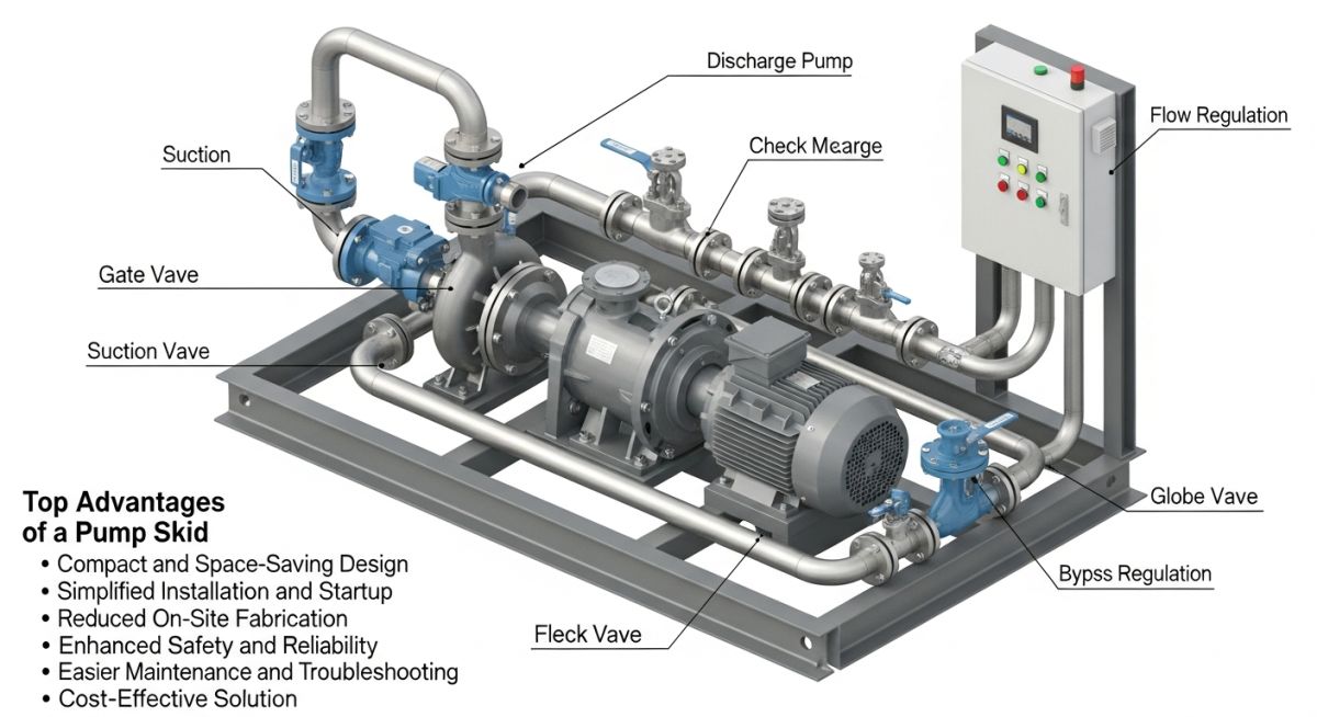
The following table outlines the standard engineering parameters and applicable codes that govern the design and fabrication of high-performance industrial pump skids.
| Design Parameter | Standard Value / Range | Applicable Code | Engineering Significance |
|---|---|---|---|
| Piping Design | Schedule 40 / 80S Minimum | ASME B31.3 | Dictates wall thickness, flange ratings, and welding procedures. |
| Structural Baseplate | ASTM A36 / Structural Steel | API 610 / ISO 13709 | Defines stiffness, coplanarity of mounting pads, and grout hole requirements. |
| Vibration Limits | Velocity < 2.8 mm/s RMS | ISO 10816 | Establishes acceptable velocity thresholds for rotating machinery. |
| Electrical Enclosures | NEMA 4X / IP66 | NEMA ICS 6 / IEC 60529 | Specifies ingress protection for hazardous or corrosive areas. |
This matrix maps the core physical components of a modular pumping system to their typical material specifications and critical inspection checkpoints.
| Component | Core Material | Design Standard | Key Inspection Checkpoint |
|---|---|---|---|
| Structural Frame | ASTM A36 / A572 Carbon Steel | AISC Manual | Weld penetration and flatness of machined mounting pads. |
| Process Piping | ASTM A312 TP316L / A106 Gr. B | ASME B31.3 | 100% Radiographic Testing (RT) on critical welds. |
| Isolation Valves | CF8M Stainless / WCB Carbon Steel | API 607 / API 598 | Seat leakage and shell pressure testing. |
| Instrumentation | 316 SS Wetted Parts | ASME B40.100 | Calibration certification and transmitter loop checks. |
How to Inspect an Industrial Pump Skid?
Before you sign off on the installation of any modular pumping package, a rigorous field inspection is required. In my experience, skipping these steps often leads to catastrophic failures during water runs or initial startup. Use this checklist to verify your installation:
Site Verification Checkpoints
-
Foundation Flatness: Verify concrete foundation flatness is within 0.125 inches (3 mm) over the entire skid footprint using a precision level.
-
Grouting Integrity: Ensure non-shrink epoxy grout is poured without voids under the structural steel frame, tapping the baseplate to listen for hollow spots.
-
Piping Strain Check: Loosen flange bolts at the skid-to-field piping interface and verify dial indicator movement on the pump shaft is less than 0.002 inches (0.05 mm) to confirm zero piping strain.
-
Electrical Grounding: Confirm the structural frame is grounded to the main plant grid at two diagonal points using minimum 2/0 AWG copper wire.
-
Instrument Calibration: Verify all pressure transmitters, flow meters, and temperature elements have valid calibration certificates and match the P&ID.
Field Case Study: Real-World Application
The Challenge: Field Fabrication Failures
A chemical processing plant in Texas attempted to field-fabricate a duplex hydrocarbon transfer pump system. Due to high ambient humidity and limited skilled labor on-site, field welding of the 6-inch Schedule 40 stainless steel piping suffered from severe carbide precipitation (weld decay). Furthermore, structural misalignment of the pump baseplates led to repeated mechanical seal failures during pre-commissioning, delaying the project by 6 weeks and costing over 120,000 in rework.
The Solution & Outcome: Modular Skid Integration
For the second phase of the expansion, I specified a fully integrated, pre-assembled industrial pump skid. The entire system was fabricated in a climate-controlled shop, where automatic orbital welding was utilized, and 100% radiography was performed. The skid underwent a full hydrostatic test and a mechanical run test (FAT) before shipping. Upon arrival, the skid was anchored, grouted, and connected to field piping within 48 hours. The system achieved immediate startup with zero vibration issues, saving 4 weeks of schedule and reducing total installation costs by 35%.
This case highlights why shop fabrication is superior. By moving the labor from the field to a controlled shop environment, we eliminated environmental variables and ensured strict adherence to quality standards.
Frequently Asked Engineering Questions
What are the primary design codes for industrial pump skids?
How do you prevent piping strain on a pump skid?
Why is factory acceptance testing (FAT) critical for pump skids?
What materials are typically used for skid structural frames?
How does a pump skid handle thermal expansion?
Can a pump skid be installed in hazardous areas?
Complete Course on
Piping Engineering
Check Now
Key Features
- 125+ Hours Content
- 500+ Recorded Lectures
- 20+ Years Exp.
- Lifetime Access
Coverage
- Codes & Standards
- Layouts & Design
- Material Eng.
- Stress Analysis
