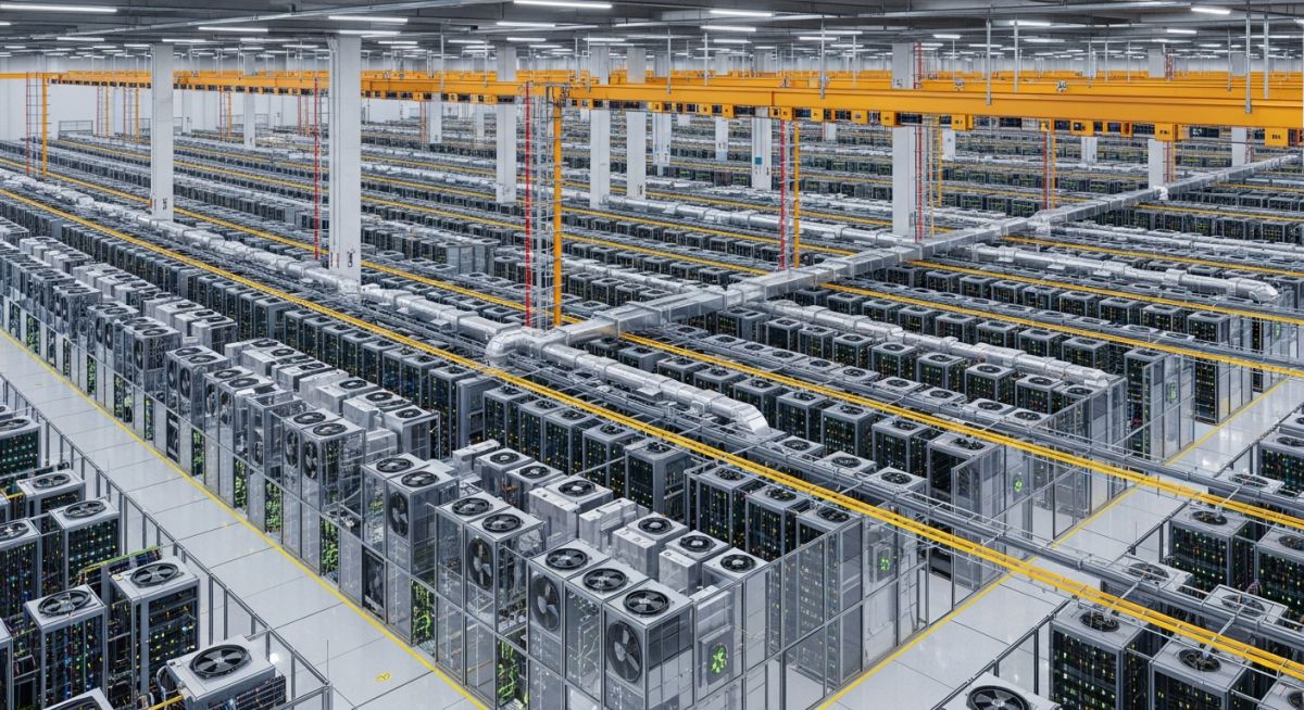
Hyperscale Data Centre Design: Engineering Principles for Scalable Infrastructure
In my two decades of experience managing large-scale mechanical and piping systems, I have observed that a hyperscale data centre is not merely a large server room; it is a complex, integrated machine. Designing these facilities requires a departure from traditional enterprise data centre methodologies, shifting toward modular, repeatable, and highly efficient infrastructure blocks.
The primary challenge lies in balancing extreme power density with the need for near-zero downtime. As we push toward higher rack densities, the mechanical systems—specifically the cooling distribution units and piping networks—become the heartbeat of the facility. This guide explores the core engineering requirements that define modern hyperscale operations.
Key Takeaways for Engineers:
- Modular design is mandatory for rapid capacity scaling.
- Power Usage Effectiveness (PUE) targets must be below 1.2.
- Redundancy must be built into the cooling loop, not just the power path.
- Thermal management is shifting from air-cooled to liquid-cooled architectures.
Engineering the Hyperscale Data Centre Infrastructure
Hyperscale Data Centre Infrastructure: The integration of high-voltage power distribution, advanced liquid cooling loops, and structural modularity designed to support massive compute loads while maintaining strict ASHRAE thermal guidelines.
When I approach the design of a hyperscale facility, I start with the power density requirements. Modern racks now frequently exceed 30kW, necessitating a transition from traditional raised-floor air cooling to direct-to-chip or rear-door heat exchangers. The calculation for total cooling load (Q) is defined by the heat dissipation of the IT equipment, where Q = m * Cp * deltaT. In a hyperscale environment, the mass flow rate (m) of the coolant must be precisely controlled to maintain the deltaT within the optimal range for chiller efficiency.
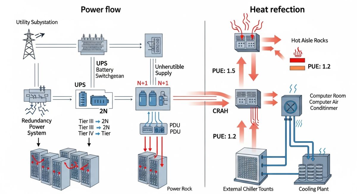
The piping network for these facilities must adhere to ASME B31.3 standards for process piping. I emphasize the use of high-density polyethylene (HDPE) or stainless steel, depending on the fluid medium and pressure requirements. A critical failure point in many designs is the lack of proper expansion loops in the chilled water headers. Given the temperature fluctuations between standby and peak load, thermal expansion can induce significant stress on pipe joints, leading to leaks that are catastrophic in a data centre environment.
Field Warning: Thermal Stress Management
Never underestimate the impact of thermal cycling on large-diameter chilled water piping. In my experience, failing to account for pipe movement at the connection points to the CRAH units is the leading cause of vibration-induced fatigue and subsequent joint failure. Always perform a formal stress analysis using software like CAESAR II for all main headers.
Power distribution follows a similar modular logic. We utilize a 415V/240V distribution architecture to minimize conversion losses. The goal is to reduce the number of transformation steps between the utility grid and the server power supply. By implementing a busway system rather than traditional cable-in-tray, we improve the flexibility of the floor layout and reduce the copper footprint, which directly contributes to a lower total cost of ownership (TCO).
Hyperscale Operational Trade-offs: The strategic balance between the economic benefits of massive scale and the technical complexities of managing high-density, mission-critical infrastructure.
Advantages
- Economies of scale significantly reduce the cost per kilowatt of installed capacity.
- Modular infrastructure allows for “pay-as-you-grow” capital expenditure models.
- Advanced automation reduces human error in routine maintenance tasks.
- Higher energy efficiency through centralized, optimized cooling plants.
- Standardized components simplify spare parts inventory and procurement.
Disadvantages
- Extreme complexity in managing massive, interconnected mechanical systems.
- High initial capital investment for site selection and utility grid connection.
- Single point of failure risks if the central cooling plant is not properly redundant.
- Difficulty in retrofitting legacy sites to meet modern high-density requirements.
- Significant environmental impact due to water consumption for evaporative cooling.
Hyperscale Deployment Scenarios: The practical implementation of large-scale data centre infrastructure across diverse sectors requiring high-performance computing and massive data storage capabilities.
Cloud Service Provider Infrastructure
These facilities serve as the backbone for global cloud platforms, requiring massive, redundant power and cooling to support thousands of virtualized server instances. The design focuses on high availability and rapid deployment of modular server pods to meet fluctuating global demand.
Artificial Intelligence Model Training
AI training clusters demand extreme power density, often exceeding 50kW per rack, necessitating advanced liquid cooling solutions. The infrastructure is engineered to minimize latency between GPU nodes, requiring specialized high-speed networking and robust thermal management systems.
High-Frequency Financial Trading
In the financial sector, hyperscale facilities are utilized to process millions of transactions per second with microsecond latency requirements. The mechanical design prioritizes extreme reliability and proximity to major network exchange points to ensure continuous, uninterrupted data flow.
Scientific Research and Genomic Sequencing
Large-scale research institutions leverage hyperscale computing to process massive datasets for genomic sequencing and climate modeling. These facilities often incorporate sustainable energy sources and advanced heat recovery systems to offset the high energy consumption of the compute clusters.
Designing a hyperscale facility requires a granular understanding of load distribution and thermal management metrics. In my experience, the transition from traditional enterprise data centres to hyperscale environments necessitates a shift toward standardized, high-density power blocks that prioritize modularity and rapid deployment. The following table outlines the critical engineering benchmarks I utilize when evaluating site feasibility and infrastructure capacity for large-scale cloud deployments.
These values represent industry-standard targets for Tier III and Tier IV facilities as defined by Uptime Institute guidelines. When reviewing these metrics, consider that power usage effectiveness (PUE) is highly dependent on the local climate and the specific cooling technology—such as liquid immersion or rear-door heat exchangers—employed within the white space.
| Parameter | Typical Range | Standard Reference |
|---|---|---|
| Rack Power Density | 15 kW to 50 kW | ASHRAE TC 9.9 |
| Target PUE | 1.10 to 1.25 | ISO/IEC 30134-2 |
| Cooling Supply Temp | 18°C to 27°C | ASHRAE Thermal Guidelines |
| Floor Loading | 12 kN/m² to 20 kN/m² | ASCE 7-22 |
Engineers must ensure that structural floor loading accounts for the increased weight of liquid cooling distribution units (CDUs) and high-density battery energy storage systems (BESS). Always verify these parameters against local seismic codes and specific equipment manufacturer specifications during the early design phase.
The complexity of a hyperscale data centre demands a rigorous mapping of mechanical, electrical, and plumbing (MEP) entities to ensure interoperability. This matrix serves as a foundational reference for project managers and lead engineers to align disparate systems—from medium-voltage utility substations to rack-level power distribution units (PDUs). By standardizing these entities, we reduce the risk of integration failures during the commissioning phase.
Each entity listed below is governed by specific international standards that dictate safety, efficiency, and operational continuity. I recommend maintaining this matrix as a living document throughout the project lifecycle, updating it as new hardware iterations or sustainability requirements emerge from the client or regulatory bodies.
| Entity | Primary Function | Standard |
|---|---|---|
| BESS | Energy Storage/UPS Backup | UL 9540 |
| CRAC/CRAH | Precision Thermal Management | ASHRAE 127 |
| MV Switchgear | Utility Power Distribution | IEC 62271 |
| Fire Suppression | Clean Agent/Water Mist | NFPA 75 |
Effective management of these entities requires a robust Building Management System (BMS) that can ingest real-time telemetry from every node. Ensure that your control logic accounts for redundant fail-safes, particularly when transitioning between utility power and on-site generation during grid instability.
Hyperscale Data Centre Site Verification: Before finalizing any site selection or commencing construction, I perform a comprehensive audit of the physical and utility infrastructure. This checklist ensures that the site meets the stringent requirements for hyperscale operations, focusing on power availability, connectivity, and environmental resilience.
-
☐
Utility Power Capacity: Verify dual-feed availability from independent substations with a minimum 100MW capacity potential. -
☐
Fiber Connectivity: Confirm access to at least three diverse carrier-neutral fiber paths with low-latency routes to major internet exchanges. -
☐
Seismic & Flood Risk: Conduct a geotechnical survey to ensure the site is outside 500-year flood zones and meets local seismic building codes. -
☐
Water Availability: Assess local water rights and infrastructure capacity for cooling systems, particularly if utilizing evaporative cooling. -
☐
Zoning & Permitting: Validate that the land use designation permits industrial data centre operations and high-voltage electrical infrastructure.
Each item on this list must be documented with a formal report signed by the lead engineer. In my experience, skipping the geotechnical or utility capacity verification often leads to catastrophic delays during the later stages of the project. Always prioritize sites that offer “shovel-ready” status with pre-approved utility easements to minimize the time-to-market for the hyperscale client.
The Problem: Thermal Runaway in High-Density Zones
A recent hyperscale project faced unexpected thermal hotspots in a high-density compute hall, leading to server throttling and potential hardware failure.
- Inadequate airflow management due to poor hot-aisle containment sealing.
- Mismatch between CRAC unit setpoints and actual rack-level intake temperatures.
- Obstruction of underfloor plenum space by legacy cabling infrastructure.
- Insufficient pressure differential between the cold aisle and the return air plenum.
The Outcome: Optimized Thermal Performance
By implementing a comprehensive remediation strategy, we successfully stabilized the thermal environment and increased overall cooling efficiency.
- Achieved a 15% reduction in fan energy consumption through VFD optimization.
- Eliminated all thermal hotspots by installing blanking panels and brush grommets.
- Improved PUE from 1.42 to 1.21 through precise airflow balancing.
- Established a real-time sensor monitoring network for predictive maintenance.
My recommendation for similar projects is to integrate Computational Fluid Dynamics (CFD) modeling during the design phase to predict airflow patterns before physical installation. This proactive approach prevents the costly retrofits required when thermal management fails to meet the demands of modern high-density hardware.
Frequently Asked Engineering Questions
What defines a hyperscale data centre?
- Capacity: Often requires 40MW to 100MW+ of critical IT load.
- Efficiency: Designed for extreme PUE optimization, often targeting 1.1 or lower.
- Architecture: Utilizes modular, repeatable building blocks for rapid scaling.
- Automation: Relies on software-defined infrastructure to manage thousands of nodes simultaneously.
How does liquid cooling impact facility design?
- Piping: Requires secondary loop distribution systems with leak detection.
- Structural: Floors must support the increased weight of CDUs and fluid-filled racks.
- Efficiency: Allows for higher inlet temperatures, reducing the need for mechanical chillers.
- Safety: Demands rigorous containment and moisture mitigation strategies to protect IT equipment.
What are the primary power distribution challenges?
- Harmonics: High-frequency switching power supplies require robust harmonic filtering.
- Voltage Drop: Long cable runs necessitate careful sizing to minimize energy loss.
- Switchgear: Requires high-interrupting capacity gear to handle potential fault currents.
- Reliability: Integration of BESS and diesel generators requires seamless transfer switching logic.
Why is PUE critical for hyperscale operators?
- Cost: Even a 0.05 improvement in PUE saves millions in annual electricity costs.
- Sustainability: Lower PUE directly correlates to a reduced carbon footprint.
- Regulatory: Many jurisdictions now mandate PUE reporting for large facilities.
- Competitive Advantage: Efficient facilities can offer lower pricing to cloud tenants.
How do you manage fire suppression in hyperscale?
- Clean Agents: Gaseous systems like FM-200 or Novec 1230 are standard for server rooms.
- Pre-action Sprinklers: Used as a secondary layer to prevent accidental discharge.
- Detection: Very Early Smoke Detection Apparatus (VESDA) is essential for early warning.
- Compliance: Systems must adhere to NFPA 75 standards for data processing facilities.
What is the role of modularity in design?
- Standardization: Using pre-fabricated power and cooling skids reduces on-site labor.
- Scalability: Facilities can expand hall-by-hall without disrupting existing operations.
- Maintenance: Modular components allow for hot-swapping without downtime.
- Speed: Prefabricated modules can be manufactured in parallel with site civil works.
Complete Course on
Piping Engineering
Check Now
Key Features
- 125+ Hours Content
- 500+ Recorded Lectures
- 20+ Years Exp.
- Lifetime Access
Coverage
- Codes & Standards
- Layouts & Design
- Material Eng.
- Stress Analysis

📚 Recommended Resources: Hyperscale Data Centre
Related posts:
![Isometric view of a modern, high-density data centre facility showing server racks, cooling systems, and cable management infrastructure.]()
Understanding Data Centre Types: Enterprise, Colocation, Hyperscale, and Edge
![Technical diagram showing the mooring spread, anchor types, buoyancy modules on dynamic cables, and subsea umbilical connections for floating wind turbines.]()
Floating Offshore Wind Technology: A Comprehensive Engineering Design Guide
![Modern data centre facility floor with organized server racks, overhead cable management, and cold-aisle containment systems.]()
How Data Centres Work: Infrastructure and Operations Engineering Overview
![Cross-sectional engineering diagram of a modern high-density data centre showing cooling and power infrastructure.]()
Data Centres Explained: A Comprehensive Engineering Design Guide
![A professional technician performing thermal inspection on a utility-scale BESS plant battery rack to ensure operational safety and efficiency.]()
Essential O&M Strategies for Reliable BESS Plant Performance Optimization
![Grid-scale lithium-ion battery energy storage system facility at sunset with modular containers and substation infrastructure.]()
Economics of Battery Energy Storage Systems: A Comprehensive Financial Guide