Hydrostatic Testing of Buried Pipelines: Comprehensive Guide (2026)
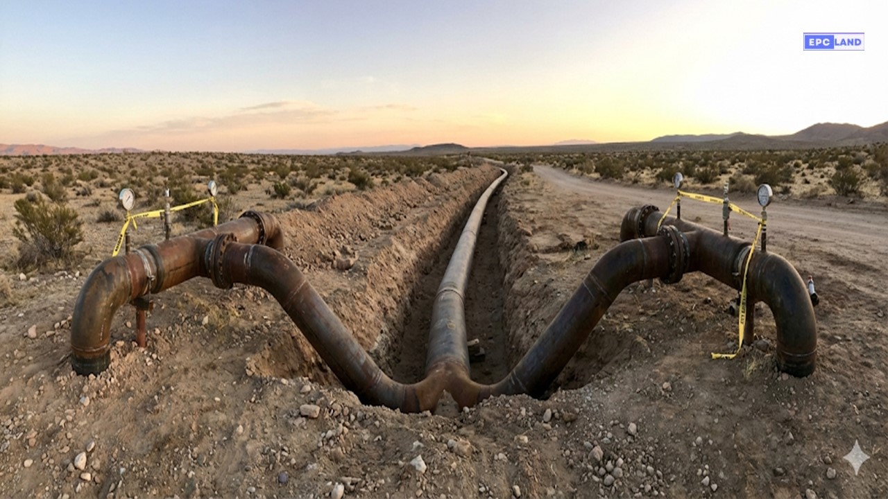
Hydrostatic Testing of Buried Pipelines is the critical final validation step in pipeline construction, designed to verify the structural integrity of the line before commissioning. Unlike above-ground piping, buried systems face unique challenges such as external soil loads, restricted access for leak detection, and elevation variances that dramatically impact static head pressure. This guide explores the engineering principles required to execute a safe and code-compliant test.
What is Hydrostatic Testing?
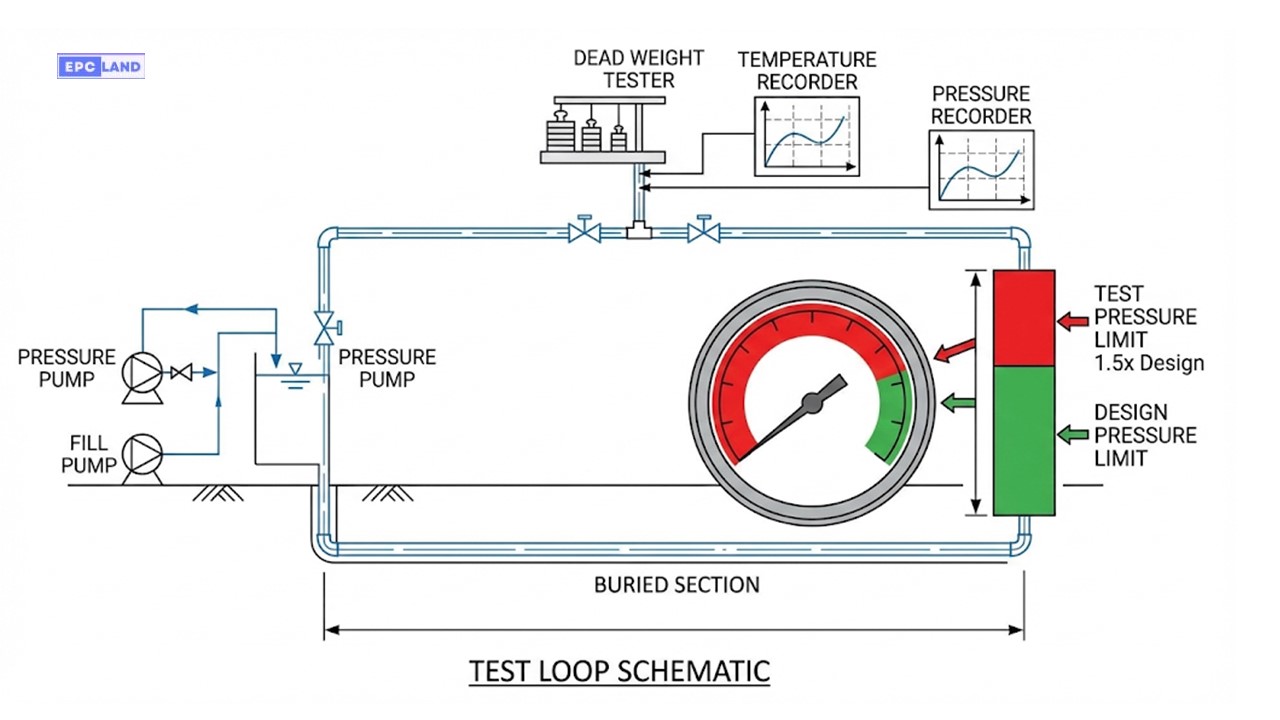
It is a non-destructive test (NDT) where a pipeline section is filled with water and pressurized to a level significantly higher than its operating pressure (typically 1.25x to 1.5x). This process verifies leak tightness and structural strength in accordance with codes like ASME B31.4 (Liquids) or ASME B31.8 (Gas).
⚡ Quick Navigation
🧪 Pre-Reading Knowledge Check
Question 1 of 51. According to ASME B31.4, what is the typical minimum hydrostatic test pressure for liquid pipelines?
Complete Course on
Piping Engineering
Check Now
Key Features
- 125+ Hours Content
- 500+ Recorded Lectures
- 20+ Years Exp.
- Lifetime Access
Coverage
- Codes & Standards
- Layouts & Design
- Material Eng.
- Stress Analysis
Engineering Theory & Code Compliance
The execution of Hydrostatic Testing of Buried Pipelines is strictly governed by international codes to ensure public safety and environmental protection. For liquid hydrocarbon pipelines, the ASME B31.4 hydrotest requirements serve as the global standard. Unlike process piping (ASME B31.3), buried pipelines interact dynamically with the soil matrix, where the overburden weight provides some restraint against thermal expansion, but also complicates leak isolation.
The testing process is generally divided into two distinct phases:
- Strength Test: A short-duration, high-pressure phase designed to mechanically stress the pipe wall to its yield limit (or a percentage thereof) to verify structural integrity.
- Leak Test: A longer-duration, slightly lower pressure phase designed to identify pinhole leaks. In many modern specifications, these are combined into a single 4 to 8-hour holding period.
Test Pressure Calculations & Physics
Determining the correct pressure is a balancing act. The pressure must be high enough to validate the Minimum Yield Strength (SMYS) but low enough to prevent plastic deformation at the lowest elevation point. Engineers use the Pipeline test pressure calculation formula derived from Barlow’s equation.
Basic Pressure Formula (ASME B31.4)
Ptest ≥ 1.25 × Pdesign
Where:
Ptest = Hydrostatic Test Pressure at high point.
Pdesign = Internal Design Pressure of the pipeline.
Hoop Stress Verification
Shoop = (Ptest × D) / (2 × t)
Shoop must not exceed 90-100% of SMYS (depending on steel grade).
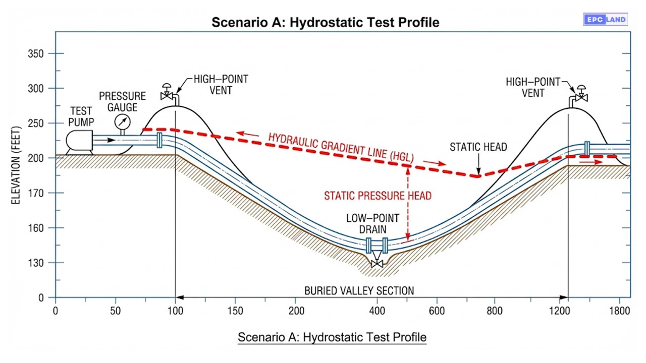
The Impact of Static Head
In Hydrostatic Testing of Buried Pipelines, elevation changes are the silent killer of test plans. Water exerts a pressure of approximately 0.433 psi per foot (or 0.098 bar per meter) of elevation.
If your test section runs through a valley that is 100 meters deeper than your injection point, the pressure at the bottom will be roughly 10 bar (145 psi) higher than at the top.
CRITICAL ENGINEERING CHECK: Ensure the pipe wall thickness at the lowest point (valley) can withstand Ptest_top + Pstatic_head without exceeding the SMYS of the material. If it exceeds limits, the pipeline must be divided into smaller test sections (Test Loops).
Code Comparison: Test Duration & Factors
| Code / Standard | Application | Min. Test Factor | Hydrotest Hold Time Duration |
|---|---|---|---|
| ASME B31.4 | Liquid Hydrocarbons (Oil) | 1.25 x MOP | 4 Continuous Hours |
| ASME B31.8 | Gas Transmission | 1.25 to 1.50 x MOP (Location Class Dependent) | 8 Continuous Hours |
| CSA Z662 | Canadian Pipelines | 1.25 x MOP | 4 Hours Strength + 4 Hours Leak |
| API 1110 | Pressure Testing Liquid Lines | See B31.4 | Recommended Practice for Execution |
*Note: Hold times refer to the period after thermal stabilization is achieved.
Execution Phase: Filling and Stabilization
1. Pigging & Filling
Before pressure can be applied, air pockets must be eliminated. Air is compressible, which stores dangerous amounts of energy and falsifies pressure readings. A medium-density foam pig is driven through the line by the water column to displace air through high-point vents.
2. Thermal Stabilization
Once filled, the water temperature and ground temperature must equilibrate. If the water is significantly warmer than the soil, the pressure will drop as the water cools and contracts, mimicking a leak.
Hydrostatic test safety exclusion zones must be established prior to pressurization, keeping non-essential personnel at least 50-100 feet away (depending on pressure class) during this volatile phase.
Case Study: Hydrostatic Testing of Buried Pipelines Failure Analysis
Project: Cross-Country Crude Oil Connector (Segment 4)
📋 Technical Specifications
Pipeline Spec:
24″ API 5L Gr. X65 (14.3mm WT)
Test Section Length:
18.5 Kilometers
Design Pressure:
100 Bar (1,450 PSI)
Target Test Pressure:
125 Bar (High Point)
The Challenge: “Phantom” Pressure Loss
During the initial 4-hour strength test, the engineering team observed a steady pressure decay of 0.8 bar per hour. While minor fluctuations are expected due to ambient temperature changes, this consistent drop suggested a potential breach. However, no water surfaced along the Right of Way (ROW).
The challenge was compounded by the terrain. The test section included a significant valley (River Crossing) where the static head added approximately 12 bar of pressure to the bottom of the line. The team feared that the combined Test Pressure + Static Head had exceeded the pipe’s yield strength at the low point, causing plastic deformation (ballooning) rather than a simple leak.
Investigation & Leak Detection
To rule out thermal contraction, the team reviewed the chart recorder data against the ground temperature probes. The “Pressure vs. Temperature” (PVT) plot showed a divergence, confirming mass loss (a leak) rather than thermal volume change.
Since the pipe was 2 meters underground, visual inspection was impossible. The team deployed advanced Buried pipeline leak detection methods. They utilized an acoustic emission survey, inserting high-sensitivity hydrophones at accessible vent points. The data triangulated a high-frequency noise signature near the river crossing isolation valve station.
Root Cause: Upon excavation, it was discovered that a 2-inch drain valve at the low point had a damaged seal. The high static pressure at the valley bottom (137 Bar total) had forced water past the valve seat, which was only rated for class 600 service (approx 100 Bar), an oversight in the temporary piping setup.
Resolution & Drying
The faulty valve was replaced with a high-pressure rated blind flange. The test was re-pressurized. The section successfully held 125 Bar for 8 hours with zero pressure drop after thermal stabilization.
Final Phase: Commissioning Prep
Once the hydrotest was certified, the team initiated dewatering and drying procedures. A series of foam pigs were run using compressed dry air (dew point -40°C) to remove all free water. This step is critical for crude oil lines to prevent internal corrosion and hydrate formation during the initial startup.
EPCLand YouTube Channel
2,500+ Videos • Daily Updates
Field Execution Protocols & Guidelines
Beyond the calculations, successful hydrotesting relies on strict adherence to field procedures. Below is the comprehensive 11-Point Checklist and execution roadmap based on ASME B31.4 standards.
Safety Assurance
Prevents catastrophic failures during operation by validating the system’s ability to contain pressure without leaking.
Regulatory Compliance
Satisfies governmental mandates (PHMSA, CER) and industry codes (ASME/API) required for operating licenses.
Integrity Verification
Mechanically stress-relieves the pipe and proves the structural soundness of welds and materials before service.
📋 The 11-Point Hydrotest Checklist
Test Medium
Standard: Water. Use inhibited glycol/methanol mix only if freezing risks exist.
Minimum Pressure
Must reach at least 1.25 times the Design Pressure (MOP) as per governing codes.
Pressurization Rate
Increase gradually (e.g., 1 bar/min) to prevent Water Hammer or shock loading damage.
Hold Period
Maintain target pressure for a minimum of 4 hours (Strength Test) to monitor stability.
Leak Test Check
Post-strength test, reduce pressure slightly and visually inspect for leaks or drops.
Temperature Monitoring
Track pipe and soil temps. 1°C change can alter pressure by ~4-5 bar (Thermal Expansion).
Safety Exclusion Zones
Keep personnel 30m+ away. Establish emergency protocols for rupture.
Joint Exposure
Where possible, leave flanges/welds exposed (unburied) during the test to visually confirm leak-tightness.
Venting Air
CRITICAL: Use high-point vents to expel ALL air. Compressed air pockets are dangerous energy stores.
Partial Backfilling
Do not fully bury the line before testing. Use center-pipe soil mounds to restrain movement, leaving joints open.
Documentation
Record P-T charts (Pressure-Temperature) continuously. Document start/end times and calibration certs.
Detailed Hydrotest Workflow
Step 1: Preparation & Inspection
Before a single drop of water enters, inspect the line for visible defects. Verify that all Pressure Testing Equipment (gauges, pumps, recorders) carries valid calibration certificates. Clear the area of non-essential personnel.
Step 2: Filling & Venting
Gradually fill the pipeline using a fill pump. Air Venting is the priority here—open high-point vents until a steady stream of water (without bubbles) flows out. Air pockets cause “spongy” pressure readings and safety hazards.
Step 3: Pressurization & Holding
Switch to a high-pressure pump. Increase pressure in stages (e.g., pause at 50% and 75% to check for leaks). Once at 100% (1.25x Design), isolate the pump. Hold the pressure for 4 hours minimum while recording the chart.
Step 4: Post-Test Recovery
Discharge: Depressurize slowly to avoid shock. Drain the medium responsibly.
Final Inspection: Check for any permanent deformation.
Report: Compile the “Hydrostatic Test Package” for sign-off.
Pressure Requirements by Material
| Pipeline Specification | Min. Hydrotest Pressure | Design Pressure Ref | Typical Test Medium |
|---|---|---|---|
| Steel Pipe (ASME B31.4) | 1.25 times Design Pressure | Varies by Class | Clean Fresh Water |
| Plastic/HDPE Pipe | 1.25 – 1.50 times Design | SDR Rating Dependent | Water / Glycol Mix |
| High-Pressure Process | 1.50 times Design Pressure | ASME B31.3 Standard | Water (Low Chloride) |
⚠️ Common Challenges
- Temperature Fluctuations: Sun exposure on exposed pipe sections can cause pressure spikes, mimicking blockages.
- Equipment Malfunctions: Leaking pump seals or faulty chart recorder pens can void a 24-hour test.
- Trapped Air: Failure to pig the line properly leads to stabilization issues and safety risks.
✅ Best Practices
- Thorough Planning: Define the “Test Pack” boundaries clearly on P&IDs before arriving on site.
- Communication: Daily toolbox talks are mandatory. Ensure every operator knows the exclusion zone limits.
- Continuous Monitoring: Use digital loggers alongside analog charts for redundancy. Never leave a pressurized line unattended.
Frequently Asked Questions
What is the standard Hydrotest hold time duration for buried lines?
Under ASME B31.4 (Liquid Pipelines), the mandatory Hydrotest hold time duration is a minimum of 4 continuous hours for the strength test. However, many operators and specific project specifications (like Shell DEP or Saudi Aramco standards) often require a combined 8-hour or even 24-hour test period to ensure sufficient time for thermal stabilization and micro-leak detection.
How do you calculate test pressure in hilly terrain?
You must calculate pressure at two distinct points: the High Point (Injection Site) and the Low Point (Valley). The pressure at the injection site is set to 1.25x Design Pressure. However, you must add the static head (0.1 bar per vertical meter) to find the pressure at the bottom. If the resulting pressure at the bottom exceeds 95-100% of the pipe’s SMYS, you must split the pipeline into shorter test sections to avoid bursting the pipe at the lowest elevation.
Can I use pneumatic testing instead of hydrostatic testing?
Pneumatic testing (using air or gas) is generally discouraged for buried pipelines due to the massive amount of stored energy. If a pneumatic line ruptures, it explodes like a bomb, whereas water (being incompressible) simply leaks out quickly with minimal blast radius. Pneumatic testing is usually reserved for low-pressure lines or Arctic environments where water freezing is a major risk, and it requires vastly larger safety exclusion zones.
What happens after the test is successful?
Post-test activities are just as critical. The line must be dewatered using pigs driven by compressed air. For hydrocarbon lines, further dewatering and drying procedures (swabbing) are required to reach a specific dew point (often -20°C to -40°C) to prevent internal corrosion or hydrate formation. Finally, the test header is cut off, and the golden tie-in weld is performed.
Final Engineering Note
Hydrostatic Testing of Buried Pipelines is the ultimate “go/no-go” gate in pipeline construction. It requires rigorous calculation of static head, strict adherence to exclusion zones, and patience during thermal stabilization. A successful test not only meets ASME B31.4 code requirements but ensures the asset is safe for decades of operation.
