Hydrogen Vessel Blast Radius: Calculating Overpressure and Safety Distances
You are standing 50 meters away from a 700-bar storage tank when a structural failure occurs. In less than 100 milliseconds, the compressed energy is no longer a fuel source—it is a devastating shockwave. While a pipe leak creates a manageable jet fire, a vessel rupture is a catastrophic release of mechanical energy. Understanding the Hydrogen Vessel Blast Radius is the difference between a safe facility layout and a multi-million dollar disaster. This guide provides the exact formulas to quantify that risk.
Core Safety Objectives
- Differentiate between Mechanical Energy release in vessels versus continuous flow in pipelines.
- Calculate TNT Equivalence using the Brode Equation for high-pressure hydrogen systems.
- Define exclusion zones based on 1.0 psi (public safety) and 3.0 psi (structural damage) overpressure limits.
What is the Hydrogen Vessel Blast Radius?
The Hydrogen Vessel Blast Radius is the calculated distance from a ruptured high-pressure tank where the resulting overpressure wave reaches specific hazard thresholds. Unlike pipe leaks, vessel blasts are determined by the TNT Equivalent of stored mechanical energy, typically requiring separation distances of 46m for buildings and 146m for public safety at 700 bar.
“In 20 years of EPC projects, I’ve seen teams confuse flame length with blast radius. A jet fire is a thermal hazard, but a vessel rupture is a structural one. You must design for the peak overpressure of the first millisecond, or the secondary fragments will do more damage than the fire itself.”
— Atul Singla, Founder
In This Technical Guide
Complete Course on
Piping Engineering
Check Now
Key Features
- 125+ Hours Content
- 500+ Recorded Lectures
- 20+ Years Exp.
- Lifetime Access
Coverage
- Codes & Standards
- Layouts & Design
- Material Eng.
- Stress Analysis
Engineering Challenge: Blast Radius Proficiency
Test your knowledge on 2026 Hydrogen Safety Standards
Question 1 of 5
Which factor primarily distinguishes a vessel blast from a pipe leak?
1. The Physics of Hydrogen Vessel Blast Radius vs. Pipe Leaks
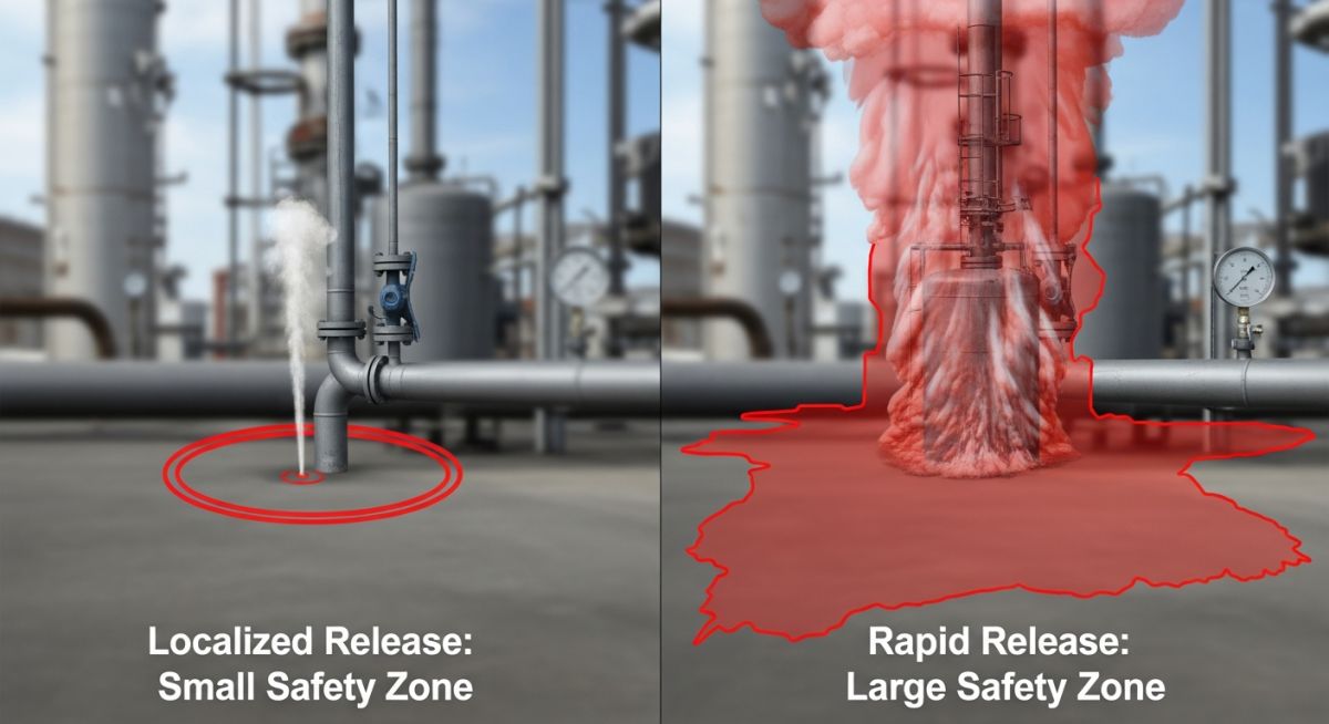
In the field of high-pressure hydrogen engineering, distinguishing between a pipeline failure and a vessel rupture is critical for accurate risk assessment. While both scenarios involve Choked Flow—where the gas reaches the speed of sound at the exit orifice—the outcome for a storage vessel is governed by a finite inventory. In a pipeline, the flow is often sustained by upstream compressors, leading to a steady-state jet fire. Conversely, a vessel rupture initiates a Blowdown Effect, where the internal pressure and mass flow rate drop exponentially as the inventory depletes.
Engineers must model the Hydrogen Vessel Blast Radius based on the initial intensity of this release. When a vessel wall fails, the gas does not just leak; it expands instantly in a “Notional Nozzle” effect, creating a hemispherical shockwave. According to the ASME B31.12 Hydrogen Piping and Pipelines standard, while pipe safety focus is on thermal radiation from jet fires, vessel safety must prioritize the overpressure wave and potential fragmentation.
2. Understanding TNT Equivalent in a Hydrogen Vessel Blast Radius
To quantify the destructive potential of a high-pressure rupture, engineers convert the stored mechanical energy into a TNT Equivalent. This allows the use of empirical blast data to predict damage distances. The primary source of energy in a hydrogen vessel is the compressed gas itself (Mechanical Energy), though if ignition occurs during the rupture, chemical energy from deflagration can contribute to the total yield.
The calculation typically employs the Brode Equation or the Abel-Noble Real Gas Equation to account for the non-ideal behavior of hydrogen at pressures exceeding 350 bar (5,000 psi). Because hydrogen molecules at 700 bar occupy significantly more volume than predicted by the Ideal Gas Law, failing to use real-gas corrections will result in an underestimation of the Hydrogen Vessel Blast Radius.
Crucial to this phase is the Efficiency Factor (η). In a physical tank burst, not 100% of the energy is converted into a shockwave; much of it is dissipated as heat or used to deform the vessel skin and propel fragments. Standard engineering practice for 2026 utilizes an efficiency factor between 5% and 10%. This refined energy value is then divided by the standard energy density of TNT (approximately 4,184 kJ/kg) to determine the weight of the equivalent explosive charge.
The Three Universes of Hydrogen Consequence Modeling
To master the Hydrogen Vessel Blast Radius, engineers must navigate three distinct physical “worlds”: Fluid Dynamics (the flow behavior), Thermodynamics (the energy storage), and Consequence Modeling (the real-world damage). Below is the grouped parameter set used in 2026 safety audits.
1. The “Source” Parameters (Internal)
- P1 (Absolute Pressure): Gauge Pressure + 1 Bar. The total potential energy source.
- T1 (Stagnation Temp): Temperature of gas at rest; critical for Joule-Thomson cooling effects.
- ρ (Density): At 700 Bar, H2 is ~40 kg/m3 (33x denser than ambient air).
- V (Volume): Defines total hazard duration and finite “Blowdown” inventory.
2. The “Leak” Parameters (Orifice)
- A (Orifice Area): The physical breach size (m2); the primary flow driver.
- Cd (Discharge Coefficient): Standardized at 0.85 to account for turbulence and vena contracta.
- γ (Ratio of Specific Heats): 1.41 for Hydrogen; dictates molecular energy storage.
- Critical Pressure Ratio: 1.899 for H2. Above this, the leak is officially “Choked.”
3. The “Atmospheric” Parameters (External)
- Patm / Tatm: Ambient conditions that dictate expansion ratios.
- τ (Transmissivity): Humidity/fog factors that absorb thermal radiation.
- Buoyancy: H2 is ~14x lighter than air, creating rapid vertical dispersion.
4. The “Hazard” & “Blast” Results
- Deff (Notional Nozzle): The “Ghost Hole” diameter after violent expansion.
- LHV (Lower Heating Value): 120 MJ/kg; the highest energy-per-weight fuel.
- Overpressure (ΔP): The crushing wave force used to define the Hydrogen Vessel Blast Radius.
- Z (Scaled Distance): The shortcut to predict damage across any tank size.
Quick Reference Glossary
| Term | The Engineering “Question” it Answers |
|---|---|
| Mach 1 | Is the gas moving at its maximum possible physical speed? |
| Choked Flow | Is the leak “maxed out” regardless of any further pressure increase? |
| Inverse Square Law | How fast does the thermal radiation dissipate as distance increases? |
| Real Gas Equation | Does the H2 act “weird” due to extreme 700 Bar compression? |
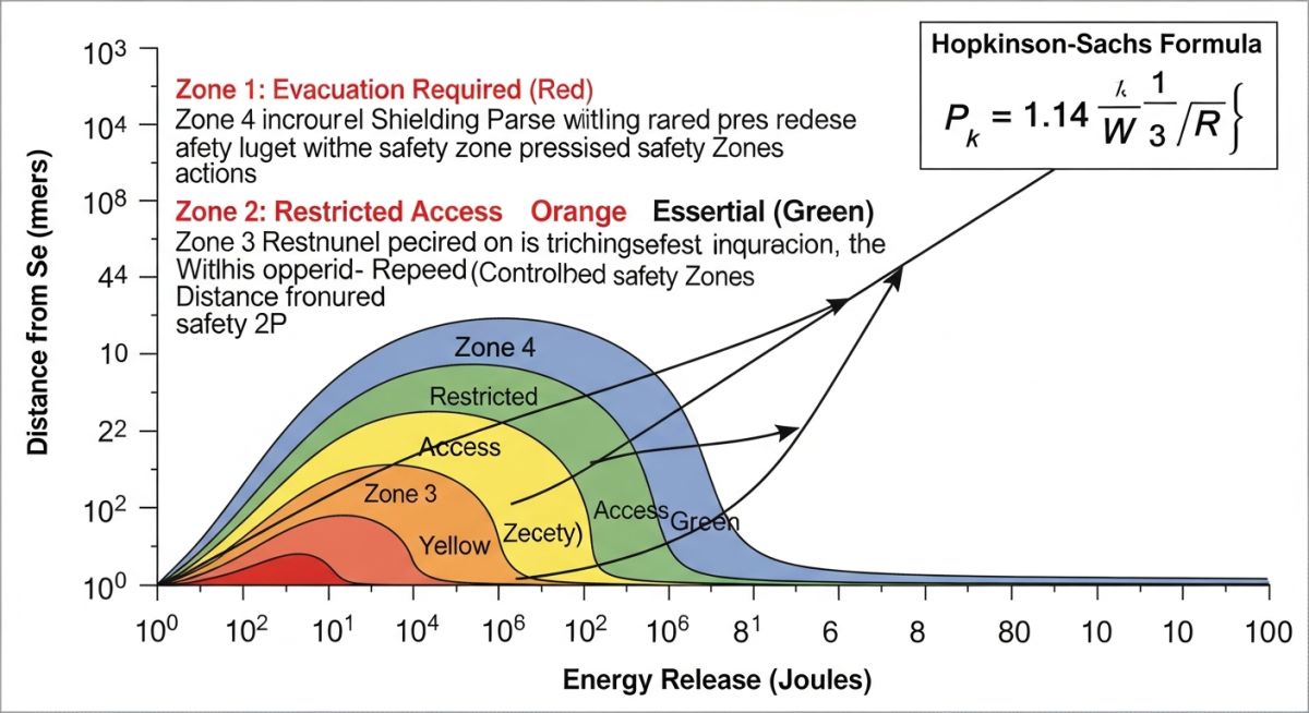
3. Calculating Overpressure: The Hopkinson-Sachs Scaling Law
Once the energy yield is converted to a mass of TNT, engineers apply the Hopkinson-Sachs Scaling Law to determine how the shockwave decays over distance. This law establishes that the Hydrogen Vessel Blast Radius is proportional to the cube root of the energy released. By calculating the “Scaled Distance” (Z), we can pinpoint the exact radial distance where the overpressure hits critical thresholds for human safety and structural integrity.
For a storage vessel operating at 700 Bar (10,000 psi), the initial blast wave is exceptionally sharp. As the wave travels outward, the peak overpressure decreases, but the duration of the impulse increases. Referencing the API RP 752/753 Standards for facility siting, we must ensure that occupied buildings are located beyond the 3.0 psi (0.20 bar) contour to prevent structural collapse and secondary debris hazards.
4. Hydrogen Vessel Blast Radius vs. Pipeline Jet Fires
The table below provides a technical comparison of the hazard profiles between a vessel failure and a pipeline rupture. This distinction is vital for 2026 site layouts where separation distances are the primary tool for risk mitigation.
| Feature | Pipe Leak / Rupture | Vessel Leak / Rupture |
|---|---|---|
| Source Volume | Often “continuous” via upstream supply. | Limited to fixed tank inventory. |
| Pressure Behavior | Sustained pressure (Steady State). | Rapid drop (Transient Blowdown). |
| Primary Hazard | Jet Fire (Thermal Radiation). | Blast Wave (Overpressure) & Fragments. |
| Isolation Strategy | Emergency Shut-Off Valves (ESVs). | Inherent design & physical separation. |
5. Safety Limits: Human and Structural Impact
In 2026, the Hydrogen Vessel Blast Radius is categorized by three critical overpressure tiers. Engineering teams use these tiers to define “Dead Zones” and “Public Access Zones” around hydrogen refueling stations and industrial electrolyzers.
- 1.0+ bar (14.5+ psi): Lethal Zone. Total demolition of reinforced structures. This radius defines the inner fence line.
- 0.20 bar (3.0 psi): Structural Damage Zone. Steel frame buildings suffer significant damage; windows and unreinforced masonry fail.
- 0.07 bar (1.0 psi): Public Safety Limit. Safe threshold for humans (ear drum safety) and glass window integrity.
Engineering Deep-Dive: Manual Blast Radius Calculations
To provide a comprehensive manual calculation, we analyze a high-pressure storage tank rupture using the Brode Equation for mechanical energy and the Highway Tanker Model for chemical yield. This represents a 2026 standard safety audit for a mid-sized hydrogen storage bank.
The Scenario: 500L H2 Storage Bank
Vessel Volume (V): 0.5 m3 (500 Liters)
Storage Pressure (P1): 700 Bar (70,000,000 Pa)
Ambient Pressure (P0): 1.013 Bar (101,325 Pa)
Heat Capacity Ratio (γ): 1.41 (Hydrogen)
Hydrogen Mass (m): ~20 kg (at 40 kg/m3 density)
LHV: 120,000 kJ/kg
Step 1: Mechanical Explosion Energy (Em)
Formula: Em = [(P1 – P0) ⋅ V] / (γ – 1)
Calculation: (69,898,675 ⋅ 0.5) / 0.41
Result: 85,242,285 Joules (85.24 MJ)
Step 2: Total TNT Equivalent (Wtotal)
Including 3% Chemical Yield (ηc) and 10% Mechanical Yield (ηm)
Effective Chem: (20kg ⋅ 120 MJ/kg) ⋅ 0.03 = 72.0 MJ
Total Energy: 80.52 MJ
Conversion: 80,520 kJ / 4,184 kJ/kg
Result: ~19.24 kg TNT Equivalent
Step 3: Calculating Hazard Perimeters
Formula: r = Z ⋅ ³√Wtotal
| Hazard Category | Overpressure | Scaled Dist (Z) | Radius (m) |
|---|---|---|---|
| Lethal Zone | 14.5 psi | 1.8 | 4.82 m |
| Structural Damage | 3.0 psi | 4.7 | 12.60 m |
| Public Safety | 1.0 psi | 14.7 | 39.40 m |
Professional Interpretation of Results
By including the Chemical Energy from an immediate fireball, the TNT Equivalent increases from 2.04 kg (Mechanical only) to 19.24 kg. This adjustment more than doubles the 1.0 psi public safety Hydrogen Vessel Blast Radius from 18.6m to 39.4m. Crucially, the Fireball Diameter (est. 25-30m) significantly overlaps the structural damage zone, meaning thermal hazards may dominate overpressure hazards within the 12-meter perimeter.
Interactive: Hydrogen Vessel Blast Radius Estimator
Use this engineering tool to estimate the Hydrogen Vessel Blast Radius and overpressure impact based on the 2026 TNT Equivalence model. Enter your vessel parameters below to see the calculated safety zones.
Estimated Safety Radii
Note: This calculator uses a simplified Brode energy model and Hopkinson-Sachs scaling. For final site layout, refer to ISO 19880-1:2026 standards.
Advanced 2026 Hydrogen Blast & Fireball Simulator
This simulator performs a high-fidelity consequence analysis by combining Mechanical Stored Energy (Brode Model) and Chemical Energy Yield (TNT Equivalence). It calculates the Hydrogen Vessel Blast Radius alongside estimated Fireball dimensions for comprehensive site siting.
Vessel Parameters
Energy Breakdown
Fireball Characteristics
Calculated Exclusion Zones
EPCLand YouTube Channel
2,500+ Videos • Daily Updates
Case Study: 700-Bar Hydrogen Refueling Station Failure Analysis
The Challenge: Urban Site Siting
In a 2026 project for a compact urban hydrogen refueling station, engineers had to determine the Hydrogen Vessel Blast Radius for a 721L storage bank operating at 700 bar. The site was constrained by a neighboring office building located 50 meters from the storage enclosure. Initial assessments based on pipeline leak models suggested a safety zone of only 15 meters, but a vessel rupture analysis revealed a different reality.
Technical Inputs
- Vessel Pressure: 700 Bar (10,150 psi)
- Inventory: 721 Liters (Type IV Tank)
- Calculated Energy: ~398 MJ (Mechanical)
- TNT Equivalent: 9.53 kg (η = 10%)
Safety Outcomes
- 3.0 psi Radius: 46 Meters
- 1.0 psi Radius: 146 Meters
- Result: The office building was within the structural damage zone.
Engineering Resolution
Relying solely on “Jet Fire” separation distances would have left the office building vulnerable to overpressure. By applying the Hydrogen Vessel Blast Radius methodology, the design team implemented a Reinforced Blast Wall and oriented the vessel longitudinal axis away from the building, effectively redirecting the shockwave and reducing the required separation distance to the property line.
Don’t miss this video related to Hydrogen

Summary: Master Piping Engineering with our complete 125+ hour Certification Course: ……
Expert Insights: Lessons from 20 years in the field
- • Energy Efficiency Factors: While historical data often used a 20% efficiency factor, modern 2026 CFD (Computational Fluid Dynamics) modeling shows that for Type IV composite tanks, the Hydrogen Vessel Blast Radius is more accurately predicted using a 5-10% range due to the energy absorbed during fiber-matrix delamination.
- • Directional Blast Effects: Vessels don’t always explode isotropically. A failure in a cylindrical tank wall often creates an elliptical Hydrogen Vessel Blast Radius. Always orient the “ends” of the tank (the caps) away from critical infrastructure, as these are the most common projectiles.
- • Real Gas Corrections: At 700 bar, the compressibility factor (Z) for hydrogen is approximately 1.45. If you use the Ideal Gas Law to calculate energy for your Hydrogen Vessel Blast Radius, you are under-calculating the potential impact by nearly 30%. Always use the Redlich-Kwong or Abel-Noble EOS.
References & Standards
Authority FAQ: Hydrogen Vessel Safety
How is the Hydrogen Vessel Blast Radius calculated?
What is a “Safe Distance” from a 700-bar hydrogen tank?
Does hydrogen ignite during a vessel rupture?
Why can’t I just use the Ideal Gas Law for these calculations?
Will a blast wall actually reduce the required safety distance?
What is the “Blowdown Effect” in vessel failures?
📚 Recommended Resources: Hydrogen
Read these Guides
- 📄 Hydrogen Separation Distance Calculation: Engineering Guide 2026
- 📄 Colors of Hydrogen: The Ultimate Engineering Guide to 10+ Production Pathways (2026)
- 📄 Green Hydrogen in Shipping: 2026 Engineering & Infrastructure Guide
- 📄 Green Hydrogen and Green Ammonia Energy Carriers: The Engineering Guide (2026)
🎓 Advanced Training


Related posts:
![High-grade industrial Wing Nut Types and Applications for mechanical assemblies.]()
Wing Nut Types and Applications: The 2026 Engineering Guide
![Industrial Monorail Crane Systems installed in a modern manufacturing plant 2026.]()
Monorail Crane Systems: Design, Types & 2026 Standards Guide
![Lead engineer performing a Factory Acceptance Test FAT on an industrial skid system 2026]()
Factory Acceptance Test FAT: The 2026 Engineering Guide to Zero-Defect Delivery
![Professional engineering workspace showing a Basis of Design document layout for a 2026 project.]()
Basis of Design: How to Write a BOD for Engineering Projects in 2026
![Industrial Flare Knockout Drum Sizing and installation in a refinery relief system.]()
Flare Knockout Drum Sizing: Design & API 521 Standards (2026 Guide)
![Advanced Reboiler Control Systems in a modern petrochemical refinery 2026.]()
Reboiler Control Systems: Engineering Guide to Precision Control 2026


