Table of Contents
Industrial Heat Exchanger Selection Guide for Piping and Process Engineers
In my 20 plus years of piping engineering experience, I have seen millions of dollars wasted on poorly specified heat exchangers. I remember a petrochemical project in 2014 where a design team selected a standard gasketed plate heat exchanger for a hydrocarbon stream containing trace amines. Within three weeks of startup, the gaskets degraded, leading to a major unscheduled shutdown. That failure was entirely preventable.
Selecting the right heat exchanger is not just about running a simulation in HTRI or Aspen; it requires a deep understanding of fluid dynamics, metallurgy, maintenance access, and mechanical design codes. In this guide, I will share the practical engineering principles I use to navigate the complex landscape of heat exchanger selection.
Key Engineering Takeaways
- Understand how fluid properties and fouling tendencies dictate shell-side versus tube-side allocation.
- Learn the mechanical limits of plate, shell-and-tube, and printed circuit heat exchangers.
- Master the application of TEMA classes and ASME Section VIII design margins.
Engineering Criteria for Industrial Heat Exchanger Selection
To achieve an optimized thermal design, we must balance the heat transfer rate with the allowable pressure drop. The fundamental heat transfer equation governs this relationship:
Q = U * A * F * LMTD
Where Q is the heat transfer rate, U is the overall heat transfer coefficient, A is the heat transfer area, F is the LMTD correction factor, and LMTD is the Logarithmic Mean Temperature Difference. The LMTD is calculated using the temperature differences at the inlets and outlets of the two fluid streams:
LMTD = (dT1 – dT2) / ln(dT1 / dT2)
The overall heat transfer coefficient (U) accounts for the convective heat transfer coefficients of both fluids and the thermal resistance of the tube wall and fouling layers:
1/U = 1/hi + Rfi + (xw / kw) + Rfo + 1/ho
Where hi and ho are the inside and outside convective heat transfer coefficients, Rfi and Rfo are the inside and outside fouling factors, xw is the tube wall thickness, and kw is the thermal conductivity of the tube material.
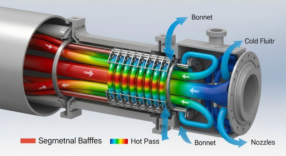
TEMA Classifications and Fluid Allocation
The Tubular Exchanger Manufacturers Association (TEMA) defines three mechanical design classes. Class R is specified for severe petroleum refining applications. Class B is intended for chemical process services, while Class C is designed for general commercial applications.
When allocating fluids to the shell or tube side, specific rules must be followed to minimize capital and maintenance costs:
- Tube-Side Allocation: Corrosive fluids (to limit expensive alloys to the tubes and channel heads), high-pressure fluids (to avoid thick shell walls), fouling fluids (for easier mechanical cleaning), and fluids with high pressure drop limitations.
- Shell-Side Allocation: Viscous fluids (to promote turbulence via baffles), condensing vapors, and boiling fluids.
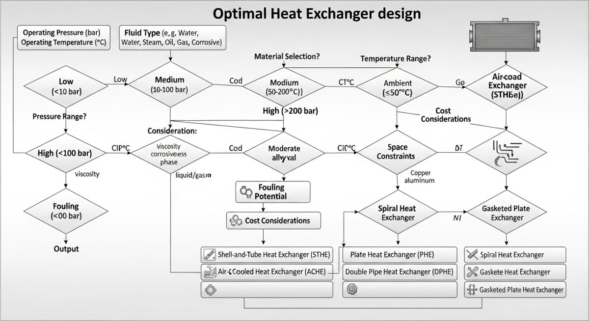
| Exchanger Type | Max Pressure (bar) | Temperature Range (°C) | Fouling Resistance | Relative Cost |
|---|---|---|---|---|
| Shell and Tube (TEMA) | 1000+ | -250 to 800 | High (Excellent cleanability) | Medium to High |
| Gasketed Plate (PHE) | 25 | -35 to 180 | Low (Self-cleaning but sensitive) | Low to Medium |
| Welded Plate (Compabloc) | 40 | -100 to 400 | Medium (Chemical cleaning required) | Medium |
| Printed Circuit (PCHE) | 600+ | -200 to 900 | Very Low (Requires clean fluids) | High |
| Spiral Heat Exchanger | 30 | -100 to 400 | Very High (Excellent for slurries) | Medium to High |
| Entity / Acronym | Technical Definition | Governing Standard | Primary Selection Driver |
|---|---|---|---|
| TEMA Class R | Heavy-duty refinery standard specifying minimum plate thicknesses and corrosion allowances. | TEMA Section 1 | Severe operating conditions and high reliability requirements. |
| PHE | Plate Heat Exchanger utilizing corrugated plates to create turbulent flow and high heat transfer. | API Standard 662 | Close temperature approach and compact footprint. |
| LMTD | Logarithmic Mean Temperature Difference representing the effective temperature driving force. | ASME Section VIII | Sizing calculations and multi-pass shell configurations. |
| PCHE | Printed Circuit Heat Exchanger manufactured via photochemical etching and diffusion bonding. | ASME Section VIII Div 1 App 44 | Extreme pressures and high-temperature gas applications. |
| Fouling Factor (Rf) | Thermal resistance introduced by dirt, scale, or chemical deposits on heat transfer surfaces. | TEMA Table RD-5 | Sizing margin and cleaning cycle frequency. |
Before introducing hot process fluids into any newly installed heat exchanger, field engineers must execute a rigorous verification protocol. Skipping these steps often leads to flange leaks, thermal shock, or premature tube failure.
Field Verification Checkpoints
-
Verify that shipping bolts and shipping brackets on floating heads or expansion joints have been completely removed. -
Confirm that the cold-tightening torque on gasketed plate heat exchangers matches the manufacturer’s minimum and maximum dimension limits (A-dimension). -
Check that nozzle piping is fully supported and aligned to prevent excessive nozzle loading under ASME B31.3 limits. -
Ensure that high-point vents and low-point drains are installed and functional on both shell and tube sides. -
Validate that the hydrostatic test pressure was held for the code-mandated duration without pressure drop or visible weeping.
Field Case Study: Real-World Application
The Problem: Rapid Fouling in Crude Preheat Train
A chemical processing facility in Texas was experiencing severe fouling in a shell-and-tube heat exchanger handling a heavy gas oil stream. The exchanger required mechanical cleaning every four months, costing over 80,000 USD per intervention in labor and lost production. The original design utilized a standard TEMA AES configuration with conventional segmental baffles, which created stagnant flow zones where carbonaceous deposits rapidly accumulated.
I led the engineering team to redesign the unit. We replaced the segmental baffles with helical baffles (TEMA AJ-shell configuration) and optimized the tube pitch from 30-degree triangular to 45-degree rotated square. This modification eliminated the low-velocity dead zones and increased shell-side shear stress. The fouling rate dropped by 55%, extending the run-length from 4 months to 18 months, saving the plant over 240,000 USD annually in maintenance costs.
Direct Recommendation: Always perform a localized velocity profile analysis (using CFD or HTRI) when dealing with high-fouling fluids. Do not rely solely on average shell-side velocities, as stagnant zones are the primary breeding ground for fouling deposits.
Common Questions on Heat Exchanger Selection
How do I choose between a shell-and-tube and a plate heat exchanger?
What is the significance of the TEMA class designations?
When should I allocate a fluid to the tube side instead of the shell side?
What is a temperature cross and how does it affect selection?
How does fouling factor affect the physical size of a heat exchanger?
What are the limitations of Printed Circuit Heat Exchangers (PCHEs)?
Complete Course on
Piping Engineering
Check Now
Key Features
- 125+ Hours Content
- 500+ Recorded Lectures
- 20+ Years Exp.
- Lifetime Access
Coverage
- Codes & Standards
- Layouts & Design
- Material Eng.
- Stress Analysis

📚 Recommended Resources: heat exchanger selection
Read these Guides
🎓 Advanced Training


Related posts:
![A restriction orifice plate installed between pipe flanges in an industrial piping system.]()
What is a Restriction Orifice? Working, Types, and Sizing Guide
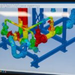
![3D CAD model of an industrial piping system showing color-coded stress analysis on a computer screen.]()
What is Pipe Stress Analysis? A Comprehensive Guide
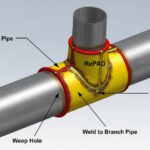
![3D CAD render of a piping reinforcement pad welded at a branch connection.]()
What is a Reinforcement Pad in Piping Design?
![Industrial parallel pipelines on a steel rack showing proper pipe spacing clearance.]()
What is Pipe Spacing and How to Use a Pipeline Spacing Chart
![Technician performing Positive Material Identification testing on industrial piping using a handheld XRF analyzer.]()
What is Positive Material Identification and Why is it Critical?
![Professional pipefitter in safety gear aligning a large steel pipe flange in an industrial facility]()
Why Pipefitters Are Critical for Industrial Piping Systems