Understanding Critical Examples of Hazards of Pressure Testing Safely
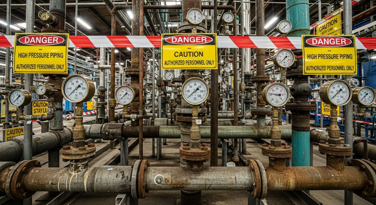
In my 20 years of managing piping systems and commissioning industrial plants, I have seen pressure testing treated as a simple check-the-box exercise. This is a dangerous mistake. Pressure testing—whether hydrostatic or pneumatic—is one of the most hazardous phases of any construction or maintenance project. When a system is pressurized, it becomes a loaded spring. If that spring releases its energy unexpectedly, the results are devastating.
I write this guide to share hard-won field insights and technical calculations. We will look at real-world examples of failures, analyze the physics of stored energy, and establish clear safety boundaries. My goal is to ensure that every engineer, inspector, and technician on your site goes home safely at the end of the day.
Key Takeaways for Field Safety
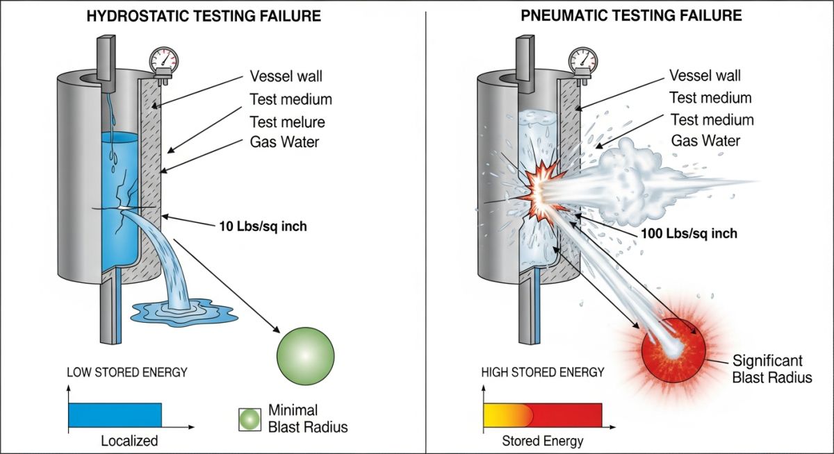
- Pneumatic testing stores up to 200 times more energy than hydrostatic testing at the same pressure.
- Brittle fracture can occur instantly if the test medium temperature is too close to the steel’s minimum design metal temperature (MDMT).
- Temporary test blinds and gaskets are the most common points of physical failure during field execution.
- Exclusion zones must be calculated using thermodynamic equations, not guessed based on site convenience.
Analyzing Real Examples of Hazards of Pressure Testing
To truly understand the risks, we must look at the physics of stored energy. The fundamental difference between hydrostatic (liquid) and pneumatic (gas) testing lies in compressibility. Water is highly incompressible, meaning it requires a massive amount of pressure to change its volume by even a fraction of a percent. Gas, on the other hand, compresses easily, packing immense potential energy into a small space.
The Thermodynamics of Pneumatic Stored Energy
When a gas-filled system ruptures, the gas expands rapidly back to atmospheric pressure. This expansion is an adiabatic process, creating a shockwave similar to a TNT explosion. We calculate this stored energy using the following thermodynamic equation:
Where:
• E is the stored energy in Joules.
• P1 is the absolute test pressure in Pascals.
• V is the total volume of the system under test in cubic meters.
• k is the ratio of specific heats of the test medium (for air or nitrogen, k is approximately 1.4).
• Pa is the atmospheric pressure (101,325 Pascals).
Let us put this into perspective. If you are pneumatically testing a 100-meter run of 12-inch Schedule 40 pipe at 20 bar (approx 2,000,000 Pascals), the stored energy is equivalent to several kilograms of TNT. If a flange fails, that energy is released in milliseconds, turning bolts and metal fragments into lethal shrapnel.
In my years on site, I have witnessed carbon steel pipes shatter like glass during cold-weather pressure tests. If the temperature of the test water or gas is below the Minimum Design Metal Temperature (MDMT) of the steel, the material loses its ductility. Always ensure your test medium is at least 17 degrees Celsius (30 degrees Fahrenheit) above the MDMT to prevent brittle fracture.
Hydrostatic Testing Hazards: Not as Safe as You Think
While hydrostatic testing is inherently safer than pneumatic testing due to lower stored energy, it is far from risk-free. A common hazard is structural overload. Water weighs 1,000 kilograms per cubic meter. If you fill a large-diameter vapor line or flare header with water for a hydrotest without verifying the structural supports, the entire piping rack can collapse.
Another major hazard is liquid jetting. A pinhole leak at 300 bar can produce a high-velocity water needle that easily cuts through leather gloves, skin, and bone. This is known as a fluid injection injury, and it requires immediate, specialized medical attention to prevent amputation.
For detailed safety guidelines on pressure testing limits, refer to the official standards on ASME B31.3 and ASME Section VIII Division 1.
The table below outlines the calculated stored energy and equivalent TNT mass for pneumatic testing across common pipe sizes and pressures. This data highlights why strict exclusion zones are mandatory.
| Pipe Size (NPS) | Length (m) | Test Pressure (bar) | Stored Energy (MJ) | TNT Equivalent (kg) | Safe Distance (m) |
|---|---|---|---|---|---|
| 6″ Sch 40 | 50 | 15 | 1.85 | 0.44 | 15 |
| 12″ Sch 40 | 100 | 20 | 15.47 | 3.70 | 35 |
| 24″ Sch 40 | 100 | 10 | 28.30 | 6.76 | 48 |
| 36″ Sch 40 | 50 | 8 | 22.10 | 5.28 | 42 |
Technical Mapping & Specifications Matrix
This matrix maps the core technical entities, structural acronyms, and physical parameters to their respective code references and safety mitigation strategies.
| Entity / Parameter | Acronym | Primary Hazard | Standard Reference | Mitigation Strategy |
|---|---|---|---|---|
| Pneumatic Testing | PT | Explosive decompression, blast wave | ASME PCC-2 Art 501 | Calculated exclusion zones, remote pressure monitoring |
| Hydrostatic Testing | HT | Structural overload, liquid jetting | ASME B31.3 Sec 345.4 | Temporary support verification, whip checks on hoses |
| Minimum Design Metal Temp | MDMT | Brittle fracture, catastrophic shattering | ASME Sec VIII Div 1 | Maintain test medium temperature at least 17°C above MDMT |
| Pressure Relief Valve | PRV | Overpressurization of test system | API RP 520 | Set PRV at 110% of test pressure or 10 psi above, whichever is greater |
Preventing Examples of Hazards of Pressure Testing
Before any valve is opened or any pump is started, the test package must be physically verified in the field. Paperwork is not enough. I have personally stopped tests where the “approved” drawing showed a blind flange that was actually a thin sheet-metal slip blind in the field. Use this checklist to verify your site is ready.
Field Verification Checkpoints
-
Isolation Verification: Ensure all test blinds are rated for the maximum test pressure. Never rely on closed inline valves for isolation; use spectacle blinds or spade blinds.
-
Gauge Calibration: Verify that at least two pressure gauges are installed, calibrated within the last 6 months, and have a range of 1.5 to 4 times the test pressure.
-
Exclusion Zone Barricading: Calculate the safe distance using ASME PCC-2 formulas. Physical barricades and warning signs must be placed around the entire perimeter.
-
Overpressure Protection: Confirm a calibrated Pressure Relief Valve (PRV) is installed on the test manifold to prevent accidental overpressurization.
-
Support Check: For hydrostatic tests, verify that temporary supports are installed for piping designed only for gas or vapor service.
-
Line Walkdown: Walk the entire line to ensure all vents are open during filling (for hydrotests) to prevent air pockets, and closed before pressurization.
Field Case Study: Real-World Application
The Problem: Catastrophic Flange Failure During Pneumatic Test
During the commissioning of a natural gas processing facility, a contractor performed a pneumatic test on a 24-inch gas header. Due to schedule pressure, they bypassed the hydrostatic test option. The test pressure was set at 45 bar.
The contractor failed to calculate the stored energy or establish a proper exclusion zone. During pressurization, at approximately 38 bar, a temporary blind flange gasket suffered a sudden blowout. The stored energy released was equivalent to 8.5 kilograms of TNT. The blast wave threw a nearby technician 10 meters, causing severe injuries, and destroyed adjacent electrical cable trays, delaying the project by four months.
The Outcome: Corrective Actions and Safety Redesign
Following the incident, I was brought in to audit their pressure testing procedures. We implemented a strict safety protocol:
- Banned pneumatic testing for all systems where hydrostatic testing is technically feasible.
- Mandated remote pressurization manifolds located at least 50 meters away from the test boundary.
- Implemented digital pressure recording to eliminate the need for technicians to approach pressurized lines to read gauges.
- Established a mandatory permit-to-work system requiring sign-off from a certified piping engineer before any test.
This case study illustrates that safety is not just about wearing PPE. It is about engineering design, rigorous calculations, and respecting the physical laws of thermodynamics.
Frequently Asked Engineering Questions
Why is pneumatic testing considered more hazardous than hydrostatic testing?
What is the minimum safe distance for a pneumatic pressure test?
How does temperature affect the safety of a pressure test?
Can we use a closed valve as an isolation point for a pressure test?
What is a fluid injection injury, and how does it occur?
What is the purpose of a pressure relief valve (PRV) during a test?
Complete Course on
Piping Engineering
Check Now
Key Features
- 125+ Hours Content
- 500+ Recorded Lectures
- 20+ Years Exp.
- Lifetime Access
Coverage
- Codes & Standards
- Layouts & Design
- Material Eng.
- Stress Analysis