Table of Contents
GRP Piping Stress Analysis Caesar II and ISO 14692 Guide
In my 20+ years of piping engineering experience, I have seen many engineers treat Glass Reinforced Plastic (GRP), Glass Reinforced Epoxy (GRE), and Fiberglass Reinforced Plastic (FRP) systems as if they were carbon steel. This is a recipe for catastrophic field failure. GRP is an anisotropic, orthotropic material. Its structural behavior is highly dependent on fiber orientation, joint types, and vendor-specific manufacturing processes.
When we perform stress analysis using Caesar II, we must shift our mindset from traditional isotropic beam theory to composite laminate mechanics. This guide details how to configure, execute, and validate GRP piping stress profiles under the strict guidance of ISO 14692 standards.
Key Engineering Takeaways
- Understand the critical differences between isotropic steel and orthotropic GRP material properties.
- Master the configuration of the ISO 14692 stress envelope within Caesar II.
- Learn how to model vendor-specific joint configurations, including adhesive-bonded and bell-and-spigot joints.
- Implement correct support spacing and design strategies to prevent localized crushing of thin-walled composite pipes.
Complete Course on
Piping Engineering
Check Now
Key Features
- 125+ Hours Content
- 500+ Recorded Lectures
- 20+ Years Exp.
- Lifetime Access
Coverage
- Codes & Standards
- Layouts & Design
- Material Eng.
- Stress Analysis
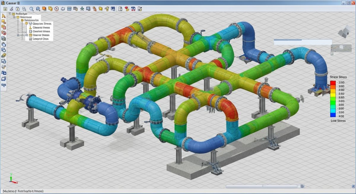
Mastering GRP Piping Stress Analysis Caesar II Workflows
To build an accurate model in Caesar II, we must first define the orthotropic material properties. Unlike steel, which has a single Elastic Modulus (E) of approximately 200,000 MPa and a Poisson’s ratio of 0.3, GRP properties vary by direction. You must input both the Axial Tensile Modulus (Ea) and the Hoop Tensile Modulus (Eh). Typically, the hoop modulus is twice as high as the axial modulus because of the filament winding angle, which is usually optimized around 55 degrees.
Orthotropic Material Inputs in Caesar II
When entering data into the Caesar II material database, you must obtain the following parameters directly from the GRP/GRE manufacturer’s technical datasheet:
- Axial Tensile Modulus (Ea): Typically ranges from 9,000 to 15,000 MPa.
- Hoop Tensile Modulus (Eh): Typically ranges from 18,000 to 28,000 MPa.
- Axial Shear Modulus (Gah): Typically ranges from 8,000 to 11,000 MPa.
- Poisson’s Ratio (v_ah and v_ha): The ratio of lateral strain to axial strain, which can range from 0.35 to 0.65 depending on the winding angle.
- Thermal Expansion Coefficients: The axial thermal expansion coefficient (alpha_a) is often significantly higher than that of carbon steel, requiring careful thermal expansion loop design.
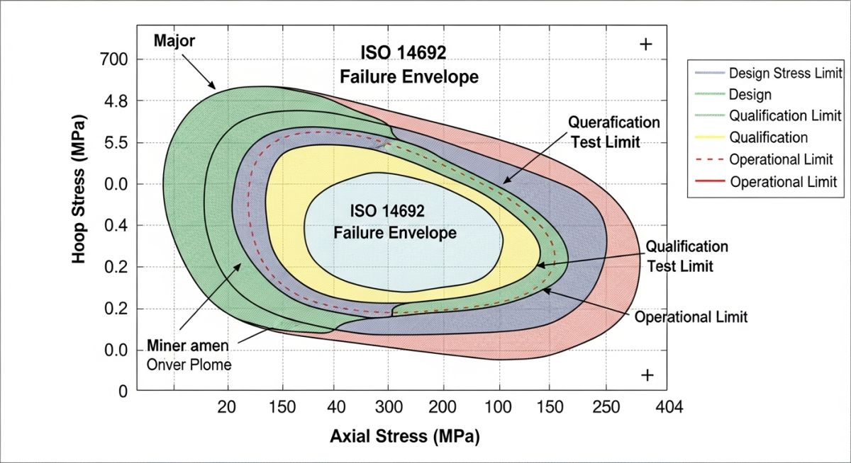
The ISO 14692 Stress Envelope
ISO 14692 utilizes a trapezoidal design envelope rather than a single allowable stress limit. This envelope represents the combined limit of axial stress and hoop stress. The envelope is scaled based on several factors:
The design factor (A_df) is applied to scale the qualified envelope down to safe operating limits. The formula for the scaled allowable stress is:
Sigma_allowable = Sigma_qualified * f_2 * f_3 * A_df
Where:
– f_2 is the temperature derating factor.
– f_3 is the chemical resistance factor (service factor).
– A_df is the design factor (typically 0.67 for sustained loads and 0.89 for short-term occasional loads).
Support Spacing and Localized Stress
Because GRP has a much lower axial modulus than steel, it is far more flexible. This flexibility results in shorter allowable support spans to control deflection. The maximum deflection is typically limited to 12.5 mm or 0.5% of the span length, whichever is smaller.
To calculate the maximum support span (L) based on deflection limits, we use the standard beam deflection equation modified for GRP properties:
L = ((384 * Ea * I * Delta_max) / (5 * w))^(1/4)
Where:
– Ea is the axial tensile modulus (N/mm²).
– I is the moment of inertia of the pipe cross-section (mm⁴).
– Delta_max is the allowable deflection (mm).
– w is the uniformly distributed load including pipe, fluid, and insulation weight (N/mm).
Material Properties Comparison
The table below highlights the stark differences between composite piping materials and standard carbon steel. These variations dictate the unique support and modeling requirements in Caesar II.
| Property | GRP (Polyester) | GRE (Epoxy) | Carbon Steel (A106-B) |
|---|---|---|---|
| Axial Modulus (Ea) | 8,000 – 12,000 MPa | 11,000 – 16,000 MPa | 203,000 MPa |
| Hoop Modulus (Eh) | 16,000 – 22,000 MPa | 20,000 – 28,000 MPa | 203,000 MPa |
| Thermal Expansion (Axial) | 20 x 10^-6 /°C | 18 x 10^-6 /°C | 11.7 x 10^-6 /°C |
| Density | 1,800 kg/m³ | 1,900 kg/m³ | 7,850 kg/m³ |
| Poisson’s Ratio (v_ah) | 0.45 – 0.55 | 0.38 – 0.48 | 0.30 |
Technical Mapping & Specifications Matrix
This matrix maps the critical design parameters defined in ISO 14692 to their corresponding input fields and analysis steps in Caesar II.
| ISO 14692 Parameter | Caesar II Input Field | Physical Significance | Verification Method |
|---|---|---|---|
| Qualified Pressure (P_q) | Internal Pressure (P1, P2) | Maximum qualified pressure from long-term testing | Must exceed design pressure including water hammer |
| Design Factor (A_df) | Allowable Stress Factor | Safety factor scaling the failure envelope | 0.67 for sustained, 0.89 for occasional loads |
| System Shear Modulus (G_ah) | Shear Modulus (G) | Governs torsional and shear deflection | Evaluated during modal and seismic analysis |
| Winding Angle (theta) | Material Configuration Screen | Determines the ratio of Ea to Eh | Used by Caesar II to calculate orthotropic stress limits |
Site Verification Checklist for GRP Piping Systems
Before finalizing any GRP stress model or releasing isometric drawings for construction, I always run through a rigorous verification process. This checklist ensures that the theoretical model in Caesar II matches the physical reality of the field installation.
Pre-Modeling & Field Installation Checkpoints
-
Vendor Datasheet Validation: Verify that the axial modulus (Ea), hoop modulus (Eh), and thermal expansion coefficients entered in Caesar II match the certified vendor data for the specific pipe class.
-
Support Width and Saddles: Ensure all support locations have a minimum contact width of 100 mm or 1/3 of the pipe diameter. Verify that wear saddles or rubber pads are modeled to prevent localized wear.
-
Joint Type Modeling: Confirm that adhesive-bonded, lamination, or bell-and-spigot joints are modeled with correct stress intensification factors (SIFs) and flexibility factors as per ISO 14692 Part 3.
-
Guide Clearances: Check that guides have a minimum clearance of 2 mm to 3 mm to prevent binding and localized stress concentration during thermal expansion.
-
Flange Alignment Limits: Verify that the maximum allowable bolt torque and flange misalignment limits specified by the manufacturer are not exceeded in the Caesar II flange leakage module.
Field Case Study: Real-World Application
The Problem: Joint Failures in a Desalination Plant
During commissioning of a seawater intake system at a major desalination facility, multiple 600 mm GRE cooling water lines suffered joint separation at the adhesive-bonded elbows. The original engineering firm had modeled the system in Caesar II using isotropic steel properties with a reduced modulus, completely ignoring the orthotropic nature of GRE and the strict stress envelope requirements of ISO 14692.
As a result, the thermal expansion of the line under solar radiation generated high axial forces that exceeded the shear capacity of the adhesive joints, leading to catastrophic leaks during hydrotesting.
The Outcome: Redesign and Validation
My team was brought in to perform a forensic stress analysis. We rebuilt the Caesar II model from scratch, inputting the correct orthotropic laminate properties (Ea = 12,500 MPa, Eh = 24,000 MPa) and applying the ISO 14692 code module. We discovered that the rigid steel anchors were trapping thermal expansion, forcing the thin-walled GRE pipe to buckle locally.
We resolved the issue by replacing three rigid anchors with guided expansion loops, adding 10 mm thick neoprene wrapping at all guide supports, and utilizing low-friction PTFE slide plates. The redesigned system successfully passed hydrotesting at 1.5 times the design pressure and has been operating trouble-free for over five years.
This case study proves that proper composite modeling is not just a theoretical exercise. It is a safety-critical requirement. By utilizing the correct code compliance modules in Caesar II, you protect both your project schedule and your field personnel.
Answering GRP Piping Stress Analysis Caesar II Queries
Why can’t I use the standard ASME B31.3 code for GRP piping stress analysis?
How does Caesar II calculate the stress ratio for GRP pipes?
What is the significance of the winding angle in GRP stress analysis?
How should I model GRP pipe supports in Caesar II to avoid local wall crushing?
What is the difference between GRP, GRE, and GRV piping?
How do I handle thermal expansion in GRP piping without expansion joints?
===

📚 Recommended Resources: GRP piping stress analysis Caesar II


Related posts:
![A mechanical sucker rod pumpjack operating in an oil field at sunset]()
What is Sucker Rod Pump System in Oil Production?
![Piping material engineer reviewing technical specifications on a tablet in an industrial plant.]()
How a Piping Material Engineer Drives Industrial Project Success
![Industrial refinery plant showing various types of static equipment]()
What is Static Equipment? Types and List of Static Equipments
![Side-by-side comparison of industrial process piping and power plant steam piping systems.]()
Differences Between ASME B31.3 and B31.1: B31.3 vs B31.1
![Large industrial steel storage tank under construction with cranes and scaffolding]()
Storage Tank Construction Method Statement: Step-by-Step Engineering Guide
![Cutaway diagram of a globe control valve highlighting the internal valve trim components]()
What is a Valve Trim? Types, Components, and Selection


