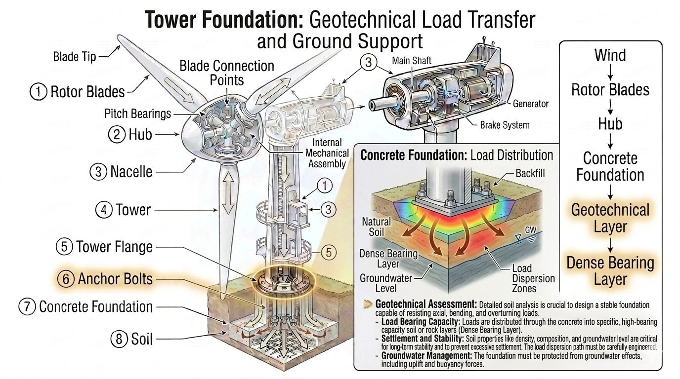
Geotechnical Load Path Design for Concrete Foundations
In my two decades of managing heavy industrial plant design, I have seen numerous foundation failures that had nothing to do with concrete strength and everything to do with neglecting the underlying soil mechanics. When massive structural loads pass from a concrete foundation into the earth, they follow a predictable geotechnical load path that requires meticulous engineering calculation. Every ton of dead, live, and seismic load must find a reliable route through backfill, natural soil, and dense bearing strata without inducing excessive settlement or rotational instability.
Designing this pathway demands a deep understanding of soil mechanics, effective stress distribution, and site-specific groundwater conditions. Whether you are anchoring high-temperature piping manifolds or supporting multi-story process columns, mastering the soil-structure interface prevents catastrophic differential settlement and structural distress.
Key Engineering Takeaways
- Loads disperse outward and downward through soil profiles, widening the effective bearing area with depth.
- Groundwater buoyancy and uplift pressures can drastically reduce effective stress and foundation stability if unmanaged.
- Bearing capacity calculations must integrate shear strength parameters (cohesion and friction angle) per ASCE standards.
- Total and differential settlement must be bounded within strict operational tolerances to protect connected piping and equipment.
Geotechnical Load Path Mechanics and Soil Mechanics
When structural engineers analyze a geotechnical load path, we evaluate how the foundation pad or pile cap interacts with the surrounding geologic medium. The journey begins at the concrete-soil interface, where vertical and lateral forces are converted into contact pressures. According to ASTM D2487 soil classification standards, the subgrade characteristics dictate whether load transfer occurs primarily via shallow bearing or deep socketing.
As loads penetrate deeper, they spread outward through a defined dispersion zone. In granular soils, this spreading follows geometric distribution rules, frequently modeled as a 2:1 vertical-to-horizontal slope. In cohesive clays, stress bulbs extend much deeper, requiring thorough consolidation testing to predict long-term primary and secondary settlement.
Bearing Capacity Formulation and Safety Factors
Ultimate bearing capacity (q_u) forms the cornerstone of foundation stability. Terzaghi’s bearing capacity equation for shallow foundations provides the fundamental framework:
Where c represents soil cohesion, q is the surcharge pressure at the footing base level, γ is the effective soil unit weight, B is the foundation width, and N_c, N_q, N_γ are dimensionless bearing capacity factors dependent on the internal friction angle (φ).
In my site designs, I apply a minimum factor of safety of 3.0 for static loads and 2.0 for combined seismic and wind load combinations, complying with ACI 336 guidelines. Ignoring local shear failure or punching shear in layered soils inevitably leads to catastrophic tilting.
Groundwater Effects on Effective Stress
Groundwater fluctuations represent one of the most hazardous variables in geotechnical load path design. The presence of a high water table alters total stress into effective stress (σ’ = σ – u), directly reducing the shear strength of frictional soils.
Critical Engineering Warning: Buoyancy and Uplift
Unmitigated hydrostatic uplift can completely neutralize foundation dead load. If buoyancy forces exceed downward structural reactions, the foundation will float or experience severe cracking. Permanent dewatering systems or structural tie-down anchors must be integrated whenever the seasonal high water table rises above the bearing elevation.
Furthermore, fluctuating saturation states induce swelling in expansive clay subgrades and liquefaction risks in loose, saturated sands during seismic events. Proper geotechnical profiling using cone penetration testing (CPT) per ASTM D5778 is mandatory.
Settlement Control and Structural Integrity
Controlling both immediate elastic settlement and long-term consolidation settlement is vital for maintaining piping alignment and equipment operability. Differential settlement induces secondary bending moments in interconnected process piping, often exceeding allowable stress limits in ASME B31.3 piping systems.
- Elastic Settlement: Calculated using linear elastic continuum mechanics based on subgrade modulus (k_s).
- Primary Consolidation: Governed by the compression index (C_c) and void ratio changes in cohesive strata.
- Secondary Compression: Creep deformation occurring under constant effective stress in organic or highly plastic clays.
By rigorously calibrating foundation bearing pressure against the preconsolidation pressure (σ’_p) of the soil, engineers ensure that the soil remains within its overconsolidated range, restricting settlement to tolerable limits.
Advantages
- Direct load transfer to dense bearing strata minimizes differential settlement risks across large industrial footprints.
- Comprehensive geotechnical profiling prevents costly redesigns by identifying weak soil anomalies early in the project lifecycle.
- Proper incorporation of groundwater buoyancy prevents unexpected structural uplift and foundation displacement.
- Optimized foundation sizing reduces concrete and reinforcing steel quantities while maintaining structural safety factors.
- Enhanced resistance against combined axial, shear, and overturning moments per ASCE 7 standards.
Disadvantages
- Extensive subsurface exploration and laboratory soil testing increase upfront engineering and investigation budgets.
- Complex groundwater control systems require continuous operational maintenance and long-term energy expenditure.
- Overly conservative bearing capacity assumptions can result in oversized foundations and excessive excavation costs.
- Unforeseen variable soil strata can render standard shallow foundation designs inadequate during construction.
- Strict settlement tolerances demand rigorous quality control during backfill compaction and subgrade preparation.
Heavy Process Column Foundations
Tall fractionation columns and distillation towers impose massive eccentric wind loads and high vertical dead weights. Engineers utilize deep octagonal mat foundations tied into dense bearing gravels to ensure load dispersion prevents excessive edge bearing pressures and rotational tilting.
High-Temperature Piping Pipe-Rack Piers
Interconnected industrial pipe racks transmit severe thermal expansion friction forces and dynamic vibration loads into foundation piers. A well-designed geotechnical load path channels these lateral shears through reinforced concrete pedestals directly into stable backfill and compacted subgrade layers.
Subsurface Storage Tank Ring Walls
Large petroleum and chemical storage tanks experience uniform ring wall loads combined with high base pressures from liquid product. Geotechnical evaluations must account for variable consolidation rates beneath the tank center versus the edge to prevent shell distortion and piping connection shear failure.
Coastal Facility Foundation Waterproofing
Industrial plants situated near coastal shorelines face severe hydrostatic uplift challenges due to tidal groundwater variations. Designing permanent drainage blankets and heavyweight mass concrete slabs ensures the structure resists buoyancy without relying solely on friction piles.
In my twenty years of managing foundation installations, I have observed that matching soil classification to its physical load-bearing parameters is where many projects succeed or fail. The geotechnical load path relies entirely on the interface between the concrete footprint and the underlying soil strata. We must evaluate how different soil profiles distribute vertical stress through their respective load dispersion zones.
The table below outlines the design parameters for common soil strata encountered during deep and shallow foundation design. These values align with ASCE 7 and standard geotechnical practices. I use these baseline figures during the initial sizing phase to ensure the load path remains stable under both static and dynamic conditions.
| Soil Classification | Presumptive Bearing Capacity (kPa) | Load Dispersion Angle (Degrees) | Typical Elastic Modulus (MPa) | Allowable Settlement Limit (mm) |
|---|---|---|---|---|
| Well-Graded Gravel (GW) | 400 – 600 | 38 – 45 | 80 – 150 | 25 |
| Coarse Sand (SW) | 250 – 400 | 32 – 38 | 50 – 80 | 25 |
| Stiff Clay (CL) | 100 – 200 | 15 – 22 | 15 – 40 | 40 |
| Silt / Sandy Silt (ML) | 75 – 150 | 20 – 28 | 10 – 30 | 30 |
Engineers must verify these presumptive values using site-specific standard penetration tests or cone penetration testing. Relying solely on generic tables without field verification can lead to differential settlement issues.
Navigating the complex regulatory and physical landscape of foundation design requires a clear understanding of how different engineering entities interact. The geotechnical load path is governed by specific physical parameters, design codes, and structural acronyms that define soil-structure interaction.
I compiled this technical mapping matrix to bridge the gap between theoretical soil mechanics and practical field execution. It links key physical parameters to their governing industry standards, such as International Building Code (IBC) guidelines. This matrix serves as a quick reference for structural engineers to verify compliance during the calculation phase.
| Technical Entity | Common Acronym | Governing Parameter | Primary Reference Standard | Field Application |
|---|---|---|---|---|
| Ultimate Bearing Capacity | q_ult | Terzaghi’s Factors (Nc, Nq, Ng) | ASTM D1586 | Sizing shallow footings and mats |
| Coefficient of Subgrade Reaction | k_s | Soil Stiffness Modulus | ASTM D1194 | Finite element foundation modeling |
| Active Earth Pressure Coefficient | K_a | Rankine / Coulomb Theory | AASHTO LRFD Bridge Design | Retaining wall and backfill design |
| Overconsolidation Ratio | OCR | Preconsolidation Pressure | ASTM D2435 | Settlement rate predictions in clay |
Understanding these relationships helps prevent design mismatches where structural stiffness exceeds the soil’s natural capacity. I always recommend cross-referencing these parameters during the initial peer review process.
Geotechnical path verification: This field protocol establishes the mandatory inspection steps required to validate soil bearing capacity, groundwater levels, and backfill compaction before pouring concrete. Compliance with ASTM D1557 ensures the foundation rests on a stable, non-yielding medium.
Before authorizing a concrete pour, I personally walk the excavation to verify that the actual field conditions match our design assumptions. Discrepancies between the geotechnical report and the open excavation are common, especially regarding groundwater seepage and localized soft spots.
-
Excavation Subgrade Inspection: Verify the subgrade is free of organic matter, standing water, or loose debris.
-
Pocket Penetrometer Testing: Conduct localized shear strength checks to confirm the presumptive bearing capacity of the natural soil layer.
-
Compaction Density Verification: Ensure backfill lifts do not exceed 150 mm and achieve 95% modified Proctor density per ASTM D1557.
-
Groundwater Level Assessment: Confirm the water table is at least 1 meter below the planned bottom of the footing, or verify that dewatering systems are active.
-
Load Dispersion Zone Clearance: Check that adjacent utility trenches do not intersect the 45-degree load dispersion envelope of the new foundation.
Field Case Study: Real-World Application
During the construction of a five-story commercial facility, our team encountered unexpected soil variations that threatened the integrity of the geotechnical load path. The design relied on a dense sand layer at three meters depth, but actual excavations revealed a highly variable silt lens.
The Problem:
The foundation excavation exposed a localized high groundwater table and low-density silt that compromised the bearing capacity.
- The natural soil layer exhibited a bearing capacity of only 90 kPa, far below the designed 250 kPa.
- Uncontrolled groundwater seepage caused piping and boiling at the base of the footing excavation.
- The load dispersion zone overlapped with a soft clay pocket, risking severe differential settlement.
- The backfill material originally delivered to the site contained high plastic clay content, making proper compaction impossible.
The Outcome:
We implemented a rapid remediation strategy that stabilized the load path and allowed construction to proceed safely.
- We installed a continuous wellpoint dewatering system to lower the groundwater level to two meters below the excavation base.
- The soft silt lens was over-excavated by 1.2 meters and replaced with controlled low-strength material (CLSM) conforming to ACI 229R.
- We substituted the clayey backfill with clean, well-graded crushed stone compacted to 98% relative density.
- Post-remediation plate load tests confirmed an allowable bearing capacity exceeding 300 kPa, with zero measurable differential settlement over the subsequent twelve months.
I recommend performing continuous subgrade probing during excavation, even if the initial geotechnical report indicates uniform soil profiles. Soil is naturally heterogeneous, and real-time field adjustments are the only way to guarantee that loads pass safely into the dense bearing layer.
Frequently Asked Engineering Questions
How does the geotechnical load path function beneath a concrete foundation?
- Structural loads apply directly to the concrete foundation slab or mat.
- Pressure disperses outward and downward through backfill and surrounding soil zones.
- The dense bearing layer absorbs the primary vertical reactions and shear forces.
What role does load dispersion play in soil profile analysis?
- Stress intensity diminishes proportionally with the square of depth below the footing base.
- Overlapping stress zones from adjacent footings can accelerate consolidation settlement.
- Boussinesq or Westergaard elastic equations quantify vertical stress distribution accurately.
How does groundwater level impact foundation stability and buoyancy?
- High water tables reduce effective soil unit weight by half through submergence.
- Buoyancy creates potential uplift hazards for empty tanks and subterranean vaults.
- Hydrostatic pressure must be relieved via perimeter drainage or counteracted with weight.
Why is a thorough geotechnical assessment critical for settlement control?
- Soil borings identify weak pockets or lenses prone to excessive secondary compression.
- Consolidation testing provides compression index values for settlement magnitude estimation.
- Foundation dimensions are calibrated to keep total and angular distortion within tolerable limits.
How do bearing capacity requirements dictate concrete foundation geometry?
- Wider footings reduce contact stress intensity on lower-capacity upper soils.
- Embedment depth increases passive resistance and overall bearing capacity limits.
- Eccentric loads require adjusted effective area calculations per ACI 318 provisions.
Field Recommendation
In my professional piping and structural design practice, ensuring a robust geotechnical load path requires decisive engineering judgment during the initial site investigation and foundation sizing phase. Based on field observations across heavy industrial facilities, I recommend the following actionable strategies for managing complex soil-structure interactions:
- If cone penetration testing reveals compressible clay layers within two footing widths of the subgrade, choose deep pile foundations or soil stabilization rather than widening shallow footings, because consolidation settlement will otherwise exceed allowable industrial limits over time.
- When high seasonal groundwater tables threaten tank foundations or heavy pump pads, always incorporate a perimeter subdrainage network coupled with a weighted slab design to resist uplift forces, rather than relying solely on chemical waterproofing membranes.
- If backfill compaction quality around massive equipment foundations falls below 95 percent Modified Proctor density, mandate mechanical recompaction before structural load application to prevent localized differential settlement and pipe nozzle stress failures.
- When designing foundations subject to high torsional and eccentric overturning moments, extend the embedment depth into the dense bearing stratum rather than merely increasing concrete thickness, as embedment significantly enhances passive soil resistance and rotational stability.
Complete Course on
Piping Engineering
Check Now
Key Features
- 125+ Hours Content
- 500+ Recorded Lectures
- 20+ Years Exp.
- Lifetime Access
Coverage
- Codes & Standards
- Layouts & Design
- Material Eng.
- Stress Analysis
