Gas-Insulated Switchgear: High-Voltage Design & Layout Guide
Over my twenty years designing utility interconnections and heavy industrial facilities, few civil engineering battles compare to the brutal spatial limits of metropolitan substations. Conventional air-insulated switchgear installations demand massive site acreage, leaving piping runs, cable trenches, and structural envelopes severely compromised.
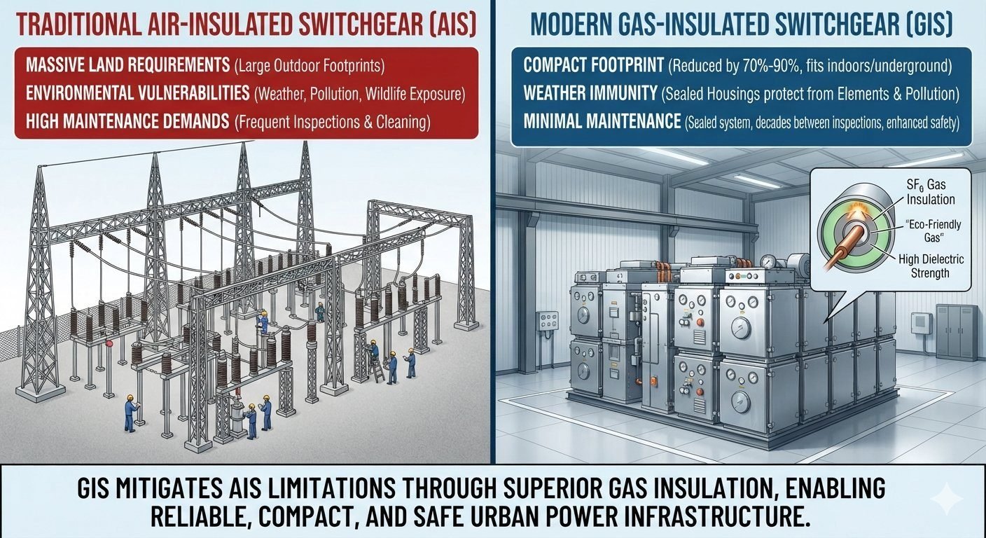
When you replace open atmospheric air clearances with sealed, pressurized dielectric gas housings, the entire layout paradigm shifts. Gas-insulated switchgear eliminates airborne corrosion risks while condensing high-voltage transmission equipment into manageable, indoor-ready basements and vertical mezzanine levels.
Core Engineering Takeaways
- Compresses land requirements by 70% to 90% compared to equivalent open-air installations.
- Hermetically sealed gas enclosures ensure total immunity against saline coastal spray and ambient industrial particulate deposition.
- Drastically lowers periodic lifecycle maintenance schedules, stretching baseline physical overhaul windows beyond twenty years.
- Demands rigorous structural anchor design and floor load qualification to support localized high mass concentrations.
Gas-Insulated Switchgear Technical Design Principles
In conventional air-insulated switchgear, atmospheric air serves as the primary dielectric medium. Atmospheric air requires expansive physical clearances to prevent flashovers across phase conductors and ground planes. A 400 kV outdoor open-air bay can easily require phase-to-earth clearances exceeding 3.4 meters and phase-to-phase separation of over 4.2 meters.
Gas-insulated switchgear substitutes atmospheric air with sulfur hexafluoride (SF6) gas held under moderate pressure, typically between 0.40 MPa and 0.65 MPa gauge at 20 degrees Celsius. At these operational pressures, the dielectric breakdown strength of SF6 is approximately three times higher than dry air at atmospheric levels, while its thermal arc-quenching capability is more than one hundred times greater.
Field Stress Warning: Liquefaction & Dynamic Reaction Limits
Gas-insulated switchgear compartments are vulnerable to extreme ambient cold. If temperature drops below the saturation curve of SF6 at rated compartment pressure (typically below -30 degrees Celsius for 0.6 MPa designs), the gas liquefies, lowering internal compartment density and gutting dielectric withstand capability. Designers must install integrated thermal insulation jackets or mixed-gas formulations like SF6/N2 mixtures compliant with IEEE C37.122.1.
Dielectric Field Equations and Clearance Calculations
The radial electric field distribution inside a coaxial, single-phase gas-insulated bus duct determines the required enclosure diameter. The electric field intensity E at any radial distance r from the inner conductor centerline is governed by:
E(r) = U / (r * ln(R_outer / R_inner))
Where U represents the applied phase-to-ground operating voltage, R_inner is the outer radius of the central tubular aluminum conductor, and R_outer is the inner radius of the grounded cylindrical enclosure shell. Maximum electrical field stress occurs directly at the surface of the conductor (r = R_inner).
To minimize the peak electric field for a fixed outer enclosure radius, you differentiate the field equation with respect to R_inner and set the derivative to zero. The mathematical optimum occurs when:
ln(R_outer / R_inner) = 1 => (R_outer / R_inner) = e ≈ 2.718
In actual utility design practice, engineers select a ratio between 2.2 and 3.0 to account for mechanical conductor stiffness, short-circuit current carrying requirements, and thermal dissipation margins under full load conditions.
Mechanical Compartmentalization and Rupture Disc Sizing
Each bay of gas-insulated switchgear is segmented into gas-tight compartments divided by gas-barrier conical or disc spacers made of cast epoxy resin. This zoning serves three critical functions:
- It prevents total gas loss across the entire substation bay during an accidental seal failure.
- It localizes volatile decomposed arc byproducts during internal high-energy fault clearance.
- It permits scheduled safe maintenance or bay extension without de-energizing adjacent live busbar sections.
Each discrete gas volume requires mechanical overpressure protection to satisfy ASME Section VIII Div 1 pressure vessel principles and IEC 62271-203 burn-through safety margins. Rupture discs must be positioned to deflect catastrophic blast energy away from standard personnel walk paths and control cabling trays.
Advantages & Disadvantages of Gas-Insulated Switchgear
Engineering Advantages
- Massive Footprint Reduction: Requires 10% to 25% of the total real estate demanded by an equivalent air-insulated switchgear yard, slashing urban land acquisition costs.
- Environmental Immunity: Enclosed grounded aluminum shells protect internal contacts, conductors, and solid insulators from salt-air corrosion, desert sandstorms, and industrial soot deposition.
- Superior Personnel Safety: The grounded exterior shell eliminates external electrical field exposure and touch-potential electrocution risks around energized conductors.
- Extended Overhaul Intervals: Sealed inert gas environments eliminate contact oxidation, allowing major maintenance-free operational intervals exceeding twenty to twenty-five years.
- Acoustic and EMI Shielding: Continuous metal enclosures attenuate electrical switching transients and magnetic interference while reducing audible corona noise to near-zero levels.
Engineering Limitations
- High Initial Capital Investment: Procurement costs for factory-manufactured gas-insulated switchgear bays run anywhere from 1.8 to 3.5 times higher than basic open-air AIS switchgear components.
- Stringent Foundation Tolerances: Heavy concentrated structural loading requires high-precision structural concrete foundations with slab flatness tolerances often exceeding 2 mm per meter.
- Complex Repair Cycles: Internal component failures demand gas evacuation, particulate filtering, vacuum drying, and high-voltage re-testing, causing prolonged repair outages.
- Environmental Regulations: SF6 carries a global warming potential 23,500 times greater than carbon dioxide, demanding intensive leak-rate tracking under environmental compliance mandates.
- Specialized Field Labor: Testing, assembly, and maintenance require specialized technicians trained in cleanroom assembly standards and high-vacuum evacuation protocol.
Real-World Applications in Industrial Infrastructure
High-Density Urban Substations
Municipal substations built within dense city cores utilize multi-story gas-insulated switchgear configurations installed entirely inside commercial architectural enclosures. This layout approach allows 230 kV or 400 kV utility feeds to integrate directly adjacent to residential properties while operating silently beneath street level.
Offshore Wind Substations & Oil Platforms
Topside weight limits and tight deck structural space require offshore high-voltage alternating current (HVAC) transformer platforms to run compact switchgear designs. Gas encapsulation prevents aggressive maritime salt spray from causing flashovers across bus supports, maintaining uninterrupted grid connectivity under harsh ocean gale conditions.
Underground Hydroelectric Caverns
Deep mountain hydroelectric generation facilities route turbine generator output through underground gas-insulated switchgear caverns directly carved into native granite rock. Compact switchgear cuts rock excavation volumes by thousands of cubic meters, routing high-voltage transmission out of the cavern via pressurized gas-insulated transmission lines (GIL).
Chemical and Heavy Petrochemical Plants
Refineries and fertilizer manufacturing complexes generate corrosive atmospheric emissions, including sulfur dioxide, chlorine vapors, and ammonia. Gas-insulated systems seal all live electrical contacts and busbars away from these aggressive ambient vapors, avoiding the accelerated corrosion and insulator flashovers that plague open-air switchgear yards.
In my 20-plus years designing substation layouts, selecting between Gas-Insulated Switchgear (GIS) and Air-Insulated Switchgear (AIS) comes down to physical clearance physics, environmental exposures, and severe spatial constraints. Air-insulated equipment relies entirely on atmospheric air as the dielectric medium, which demands extensive phase-to-phase and phase-to-ground clearances per IEEE C37.122 guidelines.
Conversely, SF6 gas provides dielectric strength roughly three times greater than atmospheric air at atmospheric pressure, and even higher when pressurized to 4.0–6.0 bar gauge. This property enables drastic physical contraction of line bays, busducts, and circuit breaker components without risking dielectric breakdown. The comparative parameters below illustrate the quantifiable engineering variances derived from project field data and standard ratings compliant with IEC 62271-203.
| Parameter | Air-Insulated Switchgear (AIS) | Gas-Insulated Switchgear (GIS) | Standard Benchmark |
|---|---|---|---|
| Insulation Medium | Atmospheric Air | Pressurized SF6 (Sulfur Hexafluoride) | IEC 62271-1 |
| Phase-to-Phase Clearance (145kV) | 1,500 mm to 1,800 mm | 120 mm to 160 mm | IEEE C37.122 |
| Substation Footprint (145kV Bay) | Approximately 1,200 m² | Approximately 100 m² to 150 m² | Substation Layout Design Manual |
| Dielectric Withstand (BIL at 145kV) | 650 kV Crest | 650 kV Crest (in reduced enclosure) | IEC 62271-203 / IEEE 1427 |
| Environmental Vulnerability | High (Salt spray, ice, pollution, fauna) | Negligible (Hermetically sealed enclosure) | ISO 12944 Corrosivity Classes |
| Major Maintenance Interval | 3 to 5 Years (Washing, contact alignment) | 20 to 25 Years (Gas monitoring, contact check) | CIGRE Working Group B3 Specifications |
| Civil Structural Building Requirement | Outdoor open yard or structural gantries | Compact indoor building or underground basement | ASCE 7 Structural Standards |
The dramatic reduction in phase clearance parameters translates directly into a 70% to 90% footprint reduction, allowing high-voltage nodes to be positioned directly inside congested urban load centers.
Evaluating gas-insulated infrastructure requires analyzing core system sub-components, physical enclosure materials, gas monitoring interfaces, and pressure safety mechanisms. Each technical entity performs a distinct dielectric or structural role within the metal-enclosed system.
The matrix below defines structural acronyms, operational thresholds, material selections, and governing standards to provide an authoritative specification reference for substation design engineers.
| Entity / Component | Physical / Operational Parameter | Standard Reference | Field Application Role |
|---|---|---|---|
| SF6 Gas (Sulfur Hexafluoride) | Dielectric constant: ~1.002; Density: 6.13 g/L at STP | IEC 60376 | Primary arc-quenching and insulating medium inside aluminum compartments. |
| Enclosure Material | Cast Aluminum Alloy (AlMg3) or Stainless Steel | ASME Sec VIII Div 1 | Maintains structural containment, prevents eddy current losses, resists external corrosion. |
| Rupture Disk Assembly | Burst Pressure: Set at 1.2x to 1.5x design operating pressure | IEC 62271-203 Clause 5.101 | Directs overpressure releases downward during internal arc faults, protecting personnel. |
| Gas Density Monitor (GDM) | Temperature-compensated switch; Alarm at 0.45 MPa, Lockout at 0.40 MPa | IEEE C37.122.1 | Provides continuous online tracking of gas pressure independent of ambient temperature shifts. |
| Post Insulators / Barrier Disks | Epoxy resin formulation; Cast with embedded stress cones | IEC 60137 | Supports internal primary conductor while isolating gas compartments mechanically. |
| Static Absorber (Desiccant) | Synthetic Zeolite / Molecular Sieve (3A to 4A pore size) | CIGRE WG B3.10 | Absorbs residual moisture inside compartments to maintain water content below 150 ppmv. |
Site Verification Protocol: Execution procedures governing structural anchoring, gas-tightness verification, moisture testing, and high-voltage dielectric withstand per IEC 62271-203 standards.
During my time overseeing GIS assembly on site, I have witnessed how minor non-conformances in vacuum handling or bolt torque can compromise an entire switchgear bay. The following technical checklist establishes strict field verification checkpoints that construction teams must sign off before energization.
Field Commissioning Validation Steps
1. Civil Structure & Structural Anchor Verification
- Verify concrete slab levelness within ±1 mm per meter to avoid mechanical strain on gas enclosure flange joints.
- Confirm expansion anchor torque matches civil design specifications according to ACI 318 standards.
- Inspect structural steel support frames for grounding continuity to the main station earth mat.
2. Gas Compartment Evacuation & Vacuum Hold Test
- Evacuate compartment to a vacuum level below 1.0 mbar (100 Pa) using a high-vacuum pump set.
- Maintain vacuum pump operation for a minimum of 2 hours after reaching target pressure to remove moisture.
- Perform a vacuum isolation hold test for 12 hours; pressure rise must not exceed 0.5 mbar.
3. SF6 Gas Filling & Purity Verification
- Fill compartment with virgin SF6 gas meeting IEC 60376 specifications up to nominal filling pressure (typically 0.55–0.60 MPa at 20°C).
- Measure gas dew point/moisture content after 24 hours of stabilization; moisture level must be below 150 ppmv.
- Verify SF6 gas purity exceeds 99.0% by volume using a calibrated gas analyzer.
4. Sniffer Leak Detection & Primary Resistance
- Scan all flanged joints, rupture disks, and density switch ports using an electronic leak detector with sensitivity of 1×10⁻6 mbar·L/s.
- Conduct main circuit resistance measurement using a 100A DC micro-ohmmeter; values must align with factory routine test reports within ±5%.
- Confirm interlocking logic between circuit breakers, disconnectors, and earthing switches per plant operating matrix.
Once these validation steps are signed off, the system is ready for high-voltage power-frequency conditioning and partial discharge testing.
Field Case Study: Real-World Application
A major metropolitan utility needed to upgrade an aging 230kV outdoor Air-Insulated Substation located in a dense downtown coastal district. The existing facility was suffering from frequent insulator flashovers driven by high salt fog corrosion from the adjacent harbor. Additionally, regional load growth required doubling transformer capacity within a parcel bounded strictly by commercial real estate.
The Problem Encountered
The existing outdoor AIS facility faced severe site limitations and escalating operational failures that rendered open-air expansion impossible:
- Land area required for a traditional 230kV AIS expansion exceeded available real estate by 400%.
- Severe marine salt spray caused dielectric tracking and flashovers on open ceramic insulators, triggering multiple unscheduled outages annually.
- Substation noise emissions exceeded municipal nighttime noise ordinances during circuit breaker switching operations.
- Seismic upgrade mandates per ASCE 7 required costly structural retrofits for tall, unsupported open-air bus structures.
The Engineering Solution & Measurable Outcome
The utility replaced the outdoor AIS layout with a 230kV indoor Gas-Insulated Switchgear configuration housed in a architecturally integrated multi-story building:
- Achieved an 88% overall footprint reduction, shrinking the substation footprint from 14,000 m² to just 1,680 m².
- Eliminated salt-spray flashover events entirely by enclosing all high-voltage live parts inside hermetically sealed SF6 aluminum enclosures.
- Dramatically lowered audible noise levels at the property boundary to below 45 dBA, meeting local municipal code.
- Freed up excess land that the utility repurposed for grid-scale battery energy storage systems (BESS).
In my experience, when real estate costs exceed 3,000 per square meter or environmental contamination risks are high, converting to an indoor GIS design delivers the lowest total lifecycle cost despite the initial equipment premium.
Frequently Asked Engineering Questions
How does the physical footprint of GIS compare directly to traditional AIS substations?
Gas-Insulated Switchgear yields a footprint reduction between 70% and 90% compared to equivalent air-insulated configurations.
- Phase clearances drop from meters in open air to centimeters within pressurized SF6 gas chambers.
- Busducts and switching elements are stacked vertically inside multi-story buildings or basement vaults.
- A standard 145kV AIS bay requires roughly 1,200 m², whereas a GIS bay fits into under 150 m².
What environmental conditions make Gas-Insulated Switchgear necessary over AIS?
GIS excels in extreme environments that degrade exposed open-air insulation systems over time.
- Coastal regions subject to severe airborne salt spray and high-humidity salt fog.
- Industrial zones with chemical emissions, heavy dust, or conductive soot accumulation.
- High-altitude or sub-zero locations prone to heavy icing, snow buildup, and severe wind loads per IEEE C37.122 standards.
What are the primary maintenance requirements for SF6 gas compartments in GIS?
Maintenance requirements for GIS are minimal compared to the routine washing and contact alignment required for AIS yard equipment.
- Continuous online monitoring of gas density using temperature-compensated pressure switches.
- Periodic moisture and purity testing of SF6 gas every 3 to 5 years according to
Complete Course on
Check Now
Piping EngineeringKey Features
- 125+ Hours Content
- 500+ Recorded Lectures
- 20+ Years Exp.
- Lifetime Access
Coverage
- Codes & Standards
- Layouts & Design
- Material Eng.
- Stress Analysis
