Preventing Galvanic Corrosion Piping Failures at Dissimilar Metal Joints
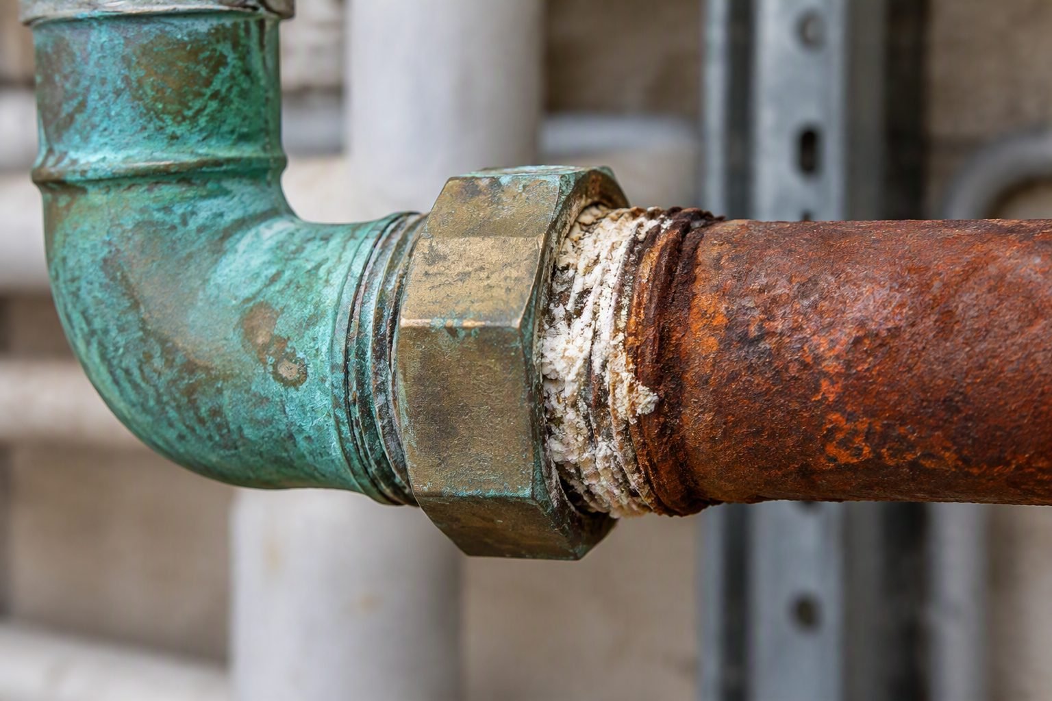
In my two decades on industrial plant sites, nothing stops a process unit quite like an unexpected leak at a threaded copper-to-steel junction. When I inspect a corroded greenish copper pipe fitting joined directly to a rusted reddish-brown steel pipe, I immediately spot the classic signature of electrochemical degradation. The visible white corrosion deposits at the thread junction tell a clear story of aggressive material loss driven by direct galvanic coupling.
Understanding how to properly isolate these dissimilar metals is mandatory for maintaining piping integrity under ASME code compliance. Without proper mechanical isolation and electrical interruption, the potential difference between copper and carbon steel creates an accelerated corrosion cell in wet service environments.
Key Design Takeaways
- Eliminate direct metal-to-metal contact between copper and steel piping systems.
- Apply ASME B31.3 compliant dielectric unions or flanged isolation kits.
- Maintain cathodic area ratios to minimize local anode consumption rates.
Electrochemical Mechanics of Galvanic Corrosion Piping Degradation
When designing process units, I always evaluate the galvanic series of metals in flowing electrolytes. Copper exhibits a noble potential of approximately plus 0.34 volts relative to the standard hydrogen electrode, whereas carbon steel sits near minus 0.44 volts. When these two metals connect directly at a threaded union, a potential difference of roughly 0.78 volts drives a massive electron flow.
The carbon steel piping acts as the sacrificial anode, experiencing localized pitting and rapid wall thinning, while the copper fitting acts as the protected cathode. In industrial cooling water or utility air systems carrying condensed moisture, this galvanic cell operates continuously until the steel threads completely disintegrate.
Critical Code Warning
Never rely on thread sealants or PTFE tape alone to prevent galvanic corrosion at dissimilar metal joints. Sealants compress under thermal cycling, creating microscopic moisture bridges that complete the electrical circuit and accelerate localized steel thread failure.
Design Rules for Dissimilar Metal Isolation
To comply with ASME B31.3 piping design rules, engineers must incorporate physical dielectric barriers wherever copper alloys meet carbon or low-alloy steels. The primary method is installing a certified dielectric union equipped with a thermoplastic insulating sleeve and gasket.
For larger pipe diameters above 2 inches where threaded unions are prohibited by pressure-temperature ratings, isolating flange kits featuring G-10 epoxy glass laminate gaskets, sleeves, and washers must be specified. These kits interrupt the electrical path while maintaining mechanical bolt load integrity under high working pressures.
Area Ratio Effects on Corrosion Kinetics
Corrosion rate is directly proportional to the cathode-to-anode surface area ratio. In many field installations, a large copper header connects to a smaller carbon steel branch line. This creates a severe unfavorable area ratio where a massive cathodic surface drives current into a tiny anodic steel surface.
Consequently, the steel pipe wall loss rate multiplies exponentially. When designing piping layouts, I always ensure that if dissimilar metals must touch, the anodic component has a significantly larger surface area than the cathodic component, or complete electrical isolation is strictly enforced.
Advantages
- Completely interrupts the electrochemical electron flow between dissimilar metal pipes.
- Extends carbon steel service life in mixed copper-steel utility networks.
- Complies directly with ASME material separation requirements for process piping.
- Reduces unplanned maintenance shutdowns caused by threaded joint leaks.
- Permits easy inspection and replacement of isolation gaskets during scheduled turnarounds.
Disadvantages
- Introduces temperature and pressure limitations based on thermoplastic sleeve materials.
- Prone to mechanical failure if subjected to excessive pipe bending or thermal shock.
- Requires rigorous installation quality control to prevent accidental electrical bridging by bolts.
- Higher initial procurement cost compared to standard carbon steel or brass fittings.
- Hidden internal sleeve degradation can cause sudden catastrophic joint failure without external warning.
Commercial HVAC Chilled Water Loops
Chilled water distribution systems frequently combine copper tubing with carbon steel headers and large-scale chillers. Without proper dielectric isolation at equipment connections, aggressive galvanic corrosion perforates steel pump casings and valve bodies within a few operating seasons.
Implementing flanged isolation kits and dielectric waterway fittings successfully prevents stray current migration across the building loops.
Chemical Plant Utility Air Lines
Instrument air and plant utility headers often transition from carbon steel distribution mains to copper branch drops supplying pneumatic control valves. Condensate accumulation inside these threaded drops creates an ideal electrolytic solution.
Using certified dielectric unions at every drop prevents white zinc and iron oxide build-up from choking off small control actuators.
Desalination and Water Treatment Plants
Seawater reverse osmosis skids utilize high-alloy copper-nickel piping coupled to lined carbon steel high-pressure vessels. The extreme salinity of the process fluid acts as a highly conductive electrolyte that accelerates galvanic attack at mechanical joints.
Engineering robust flanged isolation assemblies with coated bolts ensures long-term structural containment in corrosive marine environments.
Power Generation Condenser Systems
Steam turbine condenser cooling water circuits tie titanium or copper-alloy tube sheets directly to carbon steel water box shells. Stray electrical currents and high fluid velocities compound the galvanic potential difference between these structural metals.
Applying specialized dielectric coatings and sacrificial anode plates preserves the integrity of the carbon steel water boxes in compliance with ASME standards.
Galvanic Corrosion Compatibility Matrix
Evaluating galvanic corrosion risks in industrial piping systems requires a rigorous understanding of the electrochemical series and anode-cathode surface area ratios. When copper-based fittings interface directly with carbon or alloy steel in the presence of an electrolyte such as raw water, boiler feedwater, or condensation, a distinct galvanic cell forms. The less noble steel acts as a sacrificial anode, accelerating localized wall thinning immediately adjacent to the threaded or flanged joint. This phenomenon is governed by the potential difference between dissimilar metals as outlined in ASME B31.3 Process Piping Code.
The engineering data table below outlines galvanic potentials in seawater environments, recommended isolation methods, and standard design precautions for common industrial piping metallurgy combinations. Selecting the correct dielectric gasket set, insulating sleeve, and bolt protection washer prevents metal-to-metal contact and breaks the electrical circuit necessary for galvanic current flow. Plant integrity engineers must cross-reference fluid conductivity and operating temperatures before approving direct threaded or bolted connections between copper alloys and ferrous materials.
| Anode Material (Active) | Cathode Material (Noble) | Potential Diff (V) | ASME / ASTM Standard | Required Isolation Method |
|---|---|---|---|---|
| Carbon Steel (ASTM A53) | Copper Alloy (ASTM B88) | 0.25V – 0.45V | ASME B31.3 Table 323.1 | Dielectric Union / Flange Kit (PTFE Gasket) |
| Galvanized Steel | Stainless Steel (ASTM A312) | 0.30V – 0.50V | NACE SP0198 | Insulating Monolithic Flange Assembly |
| Aluminum (ASTM B247) | Carbon Steel (ASTM A106) | 0.15V – 0.30V | ASME PCC-1 | Neoprene Sleeve & Phenolic Washers |
| Cast Iron (ASTM A126) | Bronze Fitting (ASTM B62) | 0.20V – 0.35V | ASME B31.3 Para 335 | Epoxy-Coated Dielectric Union Assembly |
Note: Potential differentials exceeding 0.15V in wet services mandate absolute electrical isolation to prevent premature structural failure of the anode material.
Technical Mapping & Specifications Matrix
Systematic cataloging of dissimilar metal joints requires tracking specialized physical entities, material grades, and corrosion mitigation hardware. In modern hydrocarbon and utility processing units, piping designers rely on precise specification matrices to eliminate galvanic corrosion paths during the detailed engineering phase. Failure to map these parameters often results in aggressive localized pitting where copper piping interfaces with carbon steel headers or pump nozzles.
The matrix below organizes essential engineering entities, governing industry specifications, and functional deployment parameters. Each parameter aligns with strict quality assurance standards established by organizations such as ASME, ASTM, and NACE International. Utilizing these defined components ensures that piping assemblies maintain mechanical integrity across extreme thermal and pressure cycles without risking electrical continuity across the dissimilar interface.
| Entity / Component | Primary Function | Material Specification | Governing Standard | Operating Limit |
|---|---|---|---|---|
| Dielectric Gasket | Prevents direct face-to-face flange contact | PTFE / Phenolic Laminate | ASME B16.21 | Up to 250 degrees Celsius |
| Insulating Sleeve | Isolates stud bolts from flange bolt holes | Mylar / Nomex / Polyethylene | ASTM D709 | Up to 150 degrees Celsius |
| Sacrificial Anode | Provides cathodic protection via preferential corrosion | Zinc / High-Purity Magnesium | ASTM B843 | Fluid pH 6.0 to 8.5 |
| Spool Transition Piece | Separates incompatible metals via neutral buffer | Stainless Steel (ASTM A312) | ASME B31.3 | Full Rating of Piping Class |
Engineers must verify that all insulating components maintain electrical resistance greater than 10 megaohms when tested at 500V DC prior to system hydrotesting.
Dissimilar Metal Joint Verification Checklist
Field verification of dissimilar metal joints is a mandatory quality assurance gate before any piping system transitions from mechanical completion to pre-commissioning flushing. Omitting a single insulating washer or sleeve can short-circuit a dielectric union, leading to catastrophic localized wall thinning within months of startup. As a senior piping engineer, I enforce a strict multi-point inspection protocol for all copper-to-steel and alloy-to-carbon steel junctions.
The following structured verification checklist outlines the critical validation checkpoints required to ensure absolute galvanic isolation in compliance with ASME B31.3 and NACE SP0198 guidelines. Every item must be physically inspected, electrically tested, and signed off by the quality control inspector prior to thermal insulation installation.
Pre-Commissioning Dissimilar Joint Inspection Protocol
- Visual Material Identification: Verify that certified material test reports (CMTRs) match incoming piping components and that copper-to-steel direct thread connections are entirely eliminated from the isometric drawings.
- Dielectric Gasket Placement: Inspect full-face or ring dielectric gaskets for concentric alignment inside flanged joints, ensuring zero physical contact between the steel flange face and the copper alloy fitting.
- Bolt Insulating Sleeve Verification: Check that high-density polyethylene or Mylar insulating sleeves encase every stud bolt along the shank to prevent electrical bridging across the flange bolt holes.
- Insulating Washer Positioning: Confirm that phenolic or hardened steel backup washers are installed correctly beneath each nut and bolt head to protect the insulating sleeves from mechanical torque damage during tensioning.
- Electrical Resistance Testing: Perform a Megger test across the flanged joint using a 500V DC insulation tester, verifying a minimum electrical resistance reading of 10 megaohms before hydrotesting.
- External Coating and Sealing: Apply an approved moisture-resistant exterior coating or heat-shrink seal over the flanged joint to prevent external atmospheric moisture and salt spray from creating an external electrolyte bridge.
- Support and Clamping Check: Ensure that external pipe supports do not inadvertently create a secondary metallic bridge or ground path between the isolated piping sections.
Completing this checklist guarantees compliance with international piping standards and drastically extends the operating lifespan of dissimilar metal assemblies in corrosive industrial environments.
Field Case Study: Real-World Application
During a scheduled turnaround at a major coastal petrochemical processing facility, severe localized wall thinning and catastrophic leakage occurred at multiple cooling water utility junctions where copper alloy instrumentation piping tied into carbon steel distribution headers. Visible white powdery corrosion deposits and deep rust pitting characterized the failed threaded and flanged connections, threatening emergency shutdown of the cooling loop.
Problem Analysis: Galvanic Degradation at Dissimilar Metal Interface
The root cause analysis revealed an aggressive electrochemical attack driven by direct metal-to-metal contact and high-conductivity brackish cooling water.
- Direct threading of copper-nickel fittings into carbon steel couplings without dielectric isolation.
- Omission of insulating sleeves and washers during initial flange bolt-up, creating a complete electrical circuit.
- Aggressive water chemistry with elevated total dissolved solids acting as a highly active electrolyte.
- Absence of moisture barriers on exterior joint surfaces, causing secondary atmospheric corrosion bridging.
Solution & Outcome: Engineered Isolation and Long-Term Integrity
The engineering team executed a complete piping redesign and retrofit program in strict accordance with ASME B31.3 and NACE SP0198 standards.
- Replaced all direct threaded connections with monolithic insulating flange assemblies featuring PTFE gaskets and Mylar bolt sleeves.
- Verified electrical isolation exceeding 15 megaohms across every joint using calibrated 500V DC testing equipment.
- Applied high-performance moisture-cured polyurethane exterior coatings to seal the joints against atmospheric humidity.
- Achieved zero galvanic corrosion failures over five consecutive years of continuous high-salinity cooling water operation.
Engineering recommendation: Never rely on thread sealants or tape alone to prevent galvanic corrosion in dissimilar metal piping joints. Always mandate engineered dielectric isolation kits supported by rigorous pre-commissioning electrical resistance testing.
Frequently Asked Engineering Questions
What causes the white corrosion deposits at copper-steel threaded unions?
- Copper acts as a cathodic surface due to its higher nobility on the galvanic series.
- Carbon steel acts as the sacrificial anode, rapidly oxidizing and shedding mass.
- Moisture acts as the electrolyte bridge, accelerating ion transfer across the threaded interface.
- Dissolved oxygen in the process fluid fuels continuous reduction reactions at the copper cathode.
How does ASME B31.3 govern dissimilar metal piping joints?
- Paragraph 323.1 requires selecting materials resistant to fluid environments and galvanic interaction.
- Mandatory physical separation or dielectric insulation is enforced to prevent galvanic cells.
- Weld overlay or transition joint qualifications must meet strict structural integrity standards.
- Corrosion monitoring ports must be accessible near high-risk dissimilar metal transition points.
When should a dielectric union be selected over a flanged isolation kit?
- Dielectric unions typically max out at 150 to 250 psi and moderate temperatures.
- Flanged isolation kits handle ASME Class 300 ratings, high thermal cycles, and severe service fluids.
- Plastic-lined dielectric nipples can experience mechanical creep under aggressive torque loads.
- Flanged joints allow non-destructive electrical resistance testing of the isolating gasket post-installation.
What role does water chemistry play in accelerating galvanic corrosion?
- High total dissolved solids (TDS) lower electrolyte electrical resistance, boosting corrosion rates.
- Low pH levels accelerate hydrogen evolution and metal dissolution at the anodic site.
- Dissolved oxygen acts as a cathodic depolarizer, sustaining continuous metal loss.
- Scale-inhibiting chemical treatments can unintentionally alter conductivity if not carefully monitored.
How can existing corroded copper-to-steel joints be retrofitted safely?
- Isolate, depressurize, and thoroughly drain the piping segment prior to cutting.
- Remove the entire corroded threaded assembly to eliminate compromised pipe threads.
- Install a certified dielectric spool piece or flanged isolation gasket kit with proper torque specs.
- Apply external protective coatings to shield exterior surfaces from atmospheric moisture bridging.
Field Recommendation
Based on over two decades of piping engineering fieldwork managing complex utility and process infrastructure, I advise adopting these specific action items for all dissimilar metal interfaces:
- Mandatory Material Audit: If your facility handles high-salinity cooling water or process fluids exceeding 60 degrees Celsius, reject threaded dielectric unions entirely and specify ASME Class flanged isolation kits with G-10 retainer rings and Viton sleeves.
- Thread Compound Selection: When retrofitting existing copper-to-steel instrument connections where flanging is impractical, explicitly prohibit graphite-based anti-seize compounds and enforce inert PTFE tape paired with dielectric paste to eliminate internal electrolyte paths.
- External Barrier Protection: On any exterior or buried copper-to-steel transition, apply a heavy-duty moisture-displacement wax tape wrap extending at least 150 millimeters onto both parent pipes to prevent atmospheric condensation from creating an external galvanic bridge.
- Inspection Protocol Integration: Schedule ultrasonic thickness testing and visual coating inspections at every dissimilar metal joint every 24 months, treating these junctions as critical safety boundaries under your plant mechanical integrity program.
Complete Course on
Piping Engineering
Check Now
Key Features
- 125+ Hours Content
- 500+ Recorded Lectures
- 20+ Years Exp.
- Lifetime Access
Coverage
- Codes & Standards
- Layouts & Design
- Material Eng.
- Stress Analysis
