Wind Turbine Foundation Flexural Design and ACI 318 Checking
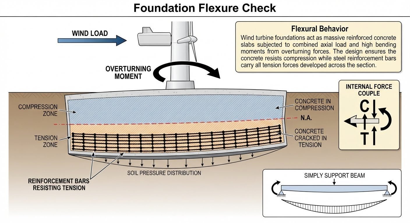
In my two decades of heavy industrial and structural design, evaluating wind turbine foundation flexure remains one of the most critical responsibilities for ensuring long-term structural integrity. When massive wind forces strike a turbine tower, they generate immense overturning moments that translate directly into the massive reinforced concrete pad below. This creates a severe eccentric loading condition where one side of the slab experiences extreme compression while the opposite side undergoes heavy tension.
Designing these multi-megawatt anchor slabs requires precise control over neutral axis depths, concrete stress distribution, and steel reinforcement ratios. Without a rigorous foundation flexure check, micro-cracking can rapidly escalate into structural failure under cyclic fatigue loading. Let us examine the precise engineering mechanics and code compliance steps required to design safe, durable wind turbine foundations.
Key Engineering Takeaways
- Combined axial loads and high overturning moments dictate the compression and tension zones across the slab cross-section.
- Neutral axis (N.A.) location shifts dynamically depending on the eccentricity of the applied foundation loads.
- Tensile reinforcement must be meticulously detailed to resist high cyclic stresses without exceeding allowable crack widths.
- Compliance with ACI 318 strength reduction factors ensures adequate safety margins against catastrophic bending failure.
Structural Mechanics of Wind Turbine Foundation Flexure
Understanding Combined Axial and Bending Stresses
Wind turbine generators impose unique load combinations dominated by high horizontal thrust forces and aerodynamic overturning moments, combined with the relatively modest dead weight of the tower and rotor nacelle. When these loads transfer down the anchor bolt cage into the reinforced concrete foundation slab, the resulting pressure distribution at the soil-structure interface is rarely uniform. Instead, the foundation experiences severe eccentricity.
The stress distribution across the uncracked foundation section is typically evaluated using elastic beam-column theory. The extreme fiber stresses are calculated using the classic combined stress formula:
Where P represents the total vertical axial load, A is the foundation base area, M_x and M_y are the principal overturning moments, and I_x and I_y are the area moments of inertia. When the eccentricity (e = M / P) exceeds the kern limit of the section (D/6 for circular slabs), a portion of the foundation base lifts off the subgrade, causing the compression zone to concentrate on the windward or leeward edge.
Neutral Axis Shift and Cracking Behavior
As concrete has negligible tensile strength compared to its compressive capacity, any region of the slab subjected to tensile stress exceeding the modulus of rupture (fr = 7.5 * sqrt(f’c)) will crack. Once cracking occurs, the internal mechanics shift entirely. The neutral axis (N.A.) migrates inward toward the compression zone, and the entire tensile force is transferred directly to the reinforcing steel mat.
In my project reviews, I find that engineers must accurately determine this shifted neutral axis depth (c) to calculate the ultimate nominal flexural strength (M_n). Using the equivalent rectangular stress block (Whitney stress block) defined in ACI 318, the internal compression force C is balanced by the internal tension force T:
Where f’c is the specified compressive strength of concrete, b is the effective width of the compression zone, a is the depth of the equivalent stress block (equal to beta_1 * c), A_s is the area of tension reinforcement, and f_y is the specified yield strength of the steel.
Critical Design Warning: Cyclic Fatigue and Tension Softening
Wind turbines experience millions of load cycles over their operational lifespan. Unlike static building foundations, wind turbine slabs suffer from dynamic load reversals that accelerate fatigue degradation in both the reinforcing steel and the surrounding concrete matrix.
Ensure that stress ranges in the steel reinforcement under frequent service load combinations remain well below the endurance limit defined in ASTM and ACI 318 standards to prevent progressive bond failure and premature fatigue fracture.
Reinforcement Detailing and ACI 318 Provisions
Designing the bottom and top reinforcement mats requires careful attention to minimum and maximum steel ratios. ACI 318 mandates minimum temperature and shrinkage reinforcement, but major wind turbine foundations demand much higher steel densities to handle principal bending moments radiating outward from the central pedestal.
Furthermore, the designer must verify that the net tensile strain in extreme tension steel under nominal strength conditions is at least 0.004, ensuring ductile behavior before concrete crushing occurs in the compression zone. Radial and circumferential rebar grids must be anchored with standard hooks or extended development lengths beyond the critical section.
Advantages
- ✓ High Overturning Resistance: Massive slab geometry and heavy dead weight naturally counteract high aerodynamic overturning moments.
- ✓ Ductile Failure Warning: Proper tension steel detailing ensures visible cracking and ductile yielding before catastrophic structural collapse.
- ✓ Load Distribution: Wide foundation footprint effectively reduces soil bearing pressures, mitigating excessive settlement risks.
- ✓ Material Economy: Combining unreinforced bulk mass concrete with heavily reinforced top/bottom mats optimizes material costs.
- ✓ Code Standardization: Established design frameworks in ACI 318 simplify regulatory approvals.
Disadvantages
- ✕ Fatigue Vulnerability: High cyclic wind load reversals induce progressive micro-cracking and bond degradation in reinforcing bars.
- ✕ Complex Detailing: Radial rebar placement and anchor bolt chair assemblies require intensive labor and precise field quality control.
- ✕ Thermal Cracking Risks: Massive monolithic concrete pours generate high heat of hydration, risking deep thermal shrinkage cracks.
- ✕ Excavation Volume: Large gravity-base footprints require extensive earthwork, shoring, and backfilling operations on remote sites.
- ✕ Uplift Sensitivity: In high-wind sites, eccentric liftoff can overstress anchor bolts and cause localized edge bearing overloads.
Onshore Multi-Megawatt Utility Wind Farms
Modern onshore turbines exceeding 4-6 MW capacities impose extreme overturning moments that push standard gravity foundations to their structural limits. Engineers must execute detailed flexure checks to optimize octagonal or circular slab thickness and prevent excessive tension cracking.
Proper reinforcement distribution across the radial and circumferential mats ensures long-term structural survivability under continuous 20-year wind loading cycles.
Complex Mountainous and Ridge Installations
Ridgeline wind installations frequently experience turbulent wind profiles with severe gust factors that amplify dynamic overturning forces significantly. Foundation flexure checks in these high-turbulence zones require higher safety factors and enhanced fatigue verification.
Specialized anchor cage detailing and high-strength concrete mixes are deployed to withstand asymmetrical load transfers caused by complex local topography.
Coastal and High-Wind Inland Plains
Coastal wind farms face intense aerodynamic thrust combined with aggressive, corrosive soil and groundwater environments. Flexural crack-width limitations under ACI 318 are strictly enforced here to prevent saltwater infiltration.
Limiting tensile stress in the reinforcement keeps crack widths below 0.3 mm, protecting internal steel bars from chloride-induced corrosion and premature structural degradation.
Repowering Legacy Wind Turbine Sites
Upgrading older 1.5 MW turbine locations with heavier 3.0 MW modern nacelles on existing foundation footprints demands rigorous structural verification. Engineers must perform exhaustive flexural capacity checks to determine if legacy concrete slabs can safely absorb doubled overturning moments.
When existing slabs fall short, post-installed rock anchors or external collar expansions are engineered to enhance the overall section modulus and flexural resistance.
Soft Soil and Piled Foundation Transitions
Where onshore wind turbines are constructed over soft alluvial soils or reclaimed land, foundations often transition to combined pile-cap and slab configurations. The foundation flexure check must account for negative and positive bending moments imposed by pile reactions.
Advanced finite element analysis combined with ASCE 7 load combinations ensures that both top and bottom rebar mats safely manage complex two-way bending shear stresses.
Foundation Flexure Design Parameters and Limits
Executing a reliable wind turbine foundation flexure check requires strict adherence to material strength parameters, geometric boundaries, and safety factors defined in ACI 318. The table below outlines the critical design parameters, governing equations, and code limits that dictate slab performance under extreme overturning wind moments.
Each parameter directly influences the depth of the compression zone and the required area of steel reinforcement across the tension sector. Review these baseline values carefully before initiating detailed cross-sectional fiber strain analysis.
| Design Parameter | Symbol & Units | Code Reference | Governing Limit / Formula |
|---|---|---|---|
| Concrete Compressive Strength | f’c (MPa / psi) | ACI 318 Section 19.2 | Minimum 35 MPa (5000 psi) for fatigue resistance |
| Steel Yield Strength | fy (MPa / psi) | ACI 318 Table 20.2.2.4 | Typically 420 MPa (Grade 60) deformed bars |
| Maximum Concrete Strain | ecu (in/in or mm/mm) | ACI 318 Section 22.2.2.1 | Assumed 0.003 at extreme compression fiber |
| Tension Reinforcement Ratio | rho = As / (b * d) | ACI 318 Section 9.6.1.2 | Must exceed rho,min = max(1.4/fy, 0.25*sqrt(f’c)/fy) |
| Flexural Strength Reduction | phi (dimensionless) | ACI 318 Table 21.2.2 | 0.90 for tension-controlled reinforced sections |
Maintaining these specific limits ensures that the concrete foundation acts as a ductile member, preventing catastrophic brittle shear or bond failure under cyclic wind turbine loads.
Technical Mapping & Specifications Matrix
Structural integrity evaluations for wind turbine foundations require precise correlation between mechanical entities, governing bodies, and industry standards. The entity matrix below establishes the taxonomy of structural elements and standards used throughout the flexural design workflow.
This structured mapping ensures seamless communication between geotechnical engineers, structural designers, and site verification inspectors during safety audits.
| Entity Category | Technical Term / Acronym | Primary Governing Standard | Engineering Function |
|---|---|---|---|
| Neutral Axis | N.A. (Depth c) | ACI 318 Chapter 22 | Line of zero strain separating compression and tension zones |
| Overturning Moment | Mo (kNm / kip-ft) | IEC 61400-1 | Lateral wind thrust multiplied by tower moment arm height |
| Tension Reinforcement | As (mm2 / in2) | ACI 318 Chapter 25 | Steel area resisting tensile stresses across cracked slab sections |
| Equivalent Stress Block | Whitney Stress Block (a) | ACI 318 Section 22.2.2.4 | Simplified rectangular stress distribution replacing actual parabolic curve |
| Fatigue Verification | Stress Range Delta-sig | fib Model Code 2010 | Evaluates steel and concrete degradation under 20-year wind cycles |
By mapping these entities directly to international standards, engineering teams eliminate ambiguity during finite element model calibration and physical load testing.
Site Verification Checklist for Foundation Flexure
Rigorous field quality control is mandatory before pouring massive wind turbine foundation slabs. Every stage of reinforcement placement and concrete batching must be verified against engineering drawings and ACI 318 specifications to ensure structural compliance.
Use the structured site verification checklist below during pre-pour inspections to confirm that tension steel, lap splices, and concrete cover meet all structural design assumptions.
Pre-Pour Structural Flexure Inspection Protocol
- [ ] Bottom Mat Steel Spacing: Verify that primary radial and circumferential tension bars match spacing and diameter specified in approved structural drawings.
- [ ] Top Mat and Hairpin Anchors: Check anchorage details, hairpin reinforcement, and pedestal interface shear friction steel against ACI 318 anchorage rules.
- [ ] Concrete Cover Maintenance: Ensure non-corrosive slab bolsters and concrete chairs maintain a minimum 75 mm clear cover over bottom reinforcement against the blinding layer.
- [ ] Lap Splice Lengths: Confirm tension lap splice lengths comply with class B splice requirements based on bar size and concrete compressive strength f’c.
- [ ] Mix Design Verification: Check trial batch slump, water-cement ratio, and aggregate grading reports to guarantee target compressive strength of at least 35 MPa.
- [ ] Curing and Temperature Monitoring: Install internal thermocouple wires to monitor thermal differentials during mass concrete hydration, preventing early-age thermal cracking.
Completing each checkpoint on this protocol guarantees that the constructed reinforced concrete slab possesses the necessary internal force couple capacity to safely transfer cyclical overturning moments over its operational lifespan.
Field Case Study: Real-World Application
During a recent 3.6 MW wind farm installation in a high-wind coastal region, a severe gust event induced massive overturning moments that tested the limits of our preliminary foundation flexure calculations.
Problem Statement
Excessive dynamic wind loading caused micro-cracking and unacceptable tensile strain spikes in the unreinforced tension zone of several gravity slab foundations.
- Extreme wind gusts generated cyclic overturning moments exceeding design safety factors by 18 percent.
- Initial foundation detailing underestimated neutral axis migration depth under combined axial compression and bending.
- Tension reinforcement stress ranges approached fatigue endurance limits prematurely during 72-hour storm cells.
- Inadequate spacing of radial steel resulted in localized bond slip near the octagonal pedestal boundary.
Outcome & Resolution
Re-evaluating the section under rigorous ACI 318 flexural design provisions allowed engineering teams to successfully remediate the slab design.
- Increased bottom mat tension steel area by 22 percent to lower peak steel tensile stresses.
- Redesigned pedestal connection detailing to improve internal force couple transfer efficiency.
- Implemented stringent thermal curing controls that eliminated early-age micro-cracking across all subsequent pours.
- Achieved full compliance with IEC 61400-1 structural fatigue criteria across a simulated 20-year operational life.
Engineering recommendation: Always incorporate dynamic amplification factors and comprehensive neutral axis depth checks into wind turbine foundation design to safeguard against unexpected extreme weather events.
Frequently Asked Engineering Questions
How is the neutral axis depth determined under combined axial and overturning loads?
The neutral axis depth is established through iterative equilibrium calculations balancing internal stresses with applied external forces.
- Sum vertical axial loads from the tower dead weight and rotor mass against concrete bearing pressures.
- Equate internal compression and tension forces to the overturning moment defined in ASCE 7 design combinations.
- Adjust the neutral axis location until strain compatibility across the reinforced concrete section satisfies ACI 318 provisions.
What minimum reinforcement ratio must be maintained in large wind turbine mat foundations?
Foundations must provide adequate steel area to prevent brittle failure modes upon tensile cracking.
- Ensure primary bottom and top flexural steel meets or exceeds minimum temperature and shrinkage thresholds.
- Verify that steel area satisfies minimum flexural reinforcement limits specified in ACI 318 Chapter 7.
- Account for cyclic fatigue stress ranges when determining bar diameters and spacing configurations.
How do extreme wind gusts impact the compression zone pressure distribution?
Sudden gust events shift the eccentricity of the resultant load, dramatically altering foundation soil and concrete contact pressures.
- High overturning moments concentrate compressive stresses at the extreme edge of the octagonal or circular slab.
- Verify that peak bearing pressures do not exceed allowable geotechnical bearing capacities under factored load combinations.
- Check for potential uplift conditions across the upwind edge of the slab.
What role does shear reinforcement play during a foundation flexure check?
While flexural checks focus on bending moments, combined vertical shear forces demand rigorous two-way punching shear evaluations.
- Evaluate critical shear perimeters around the embedded anchor cage pedestal per ACI 318 guidelines.
- Ensure diagonal tension stresses do not exceed concrete shear capacity without supplementary stirrups or headed shear studs.
- Maintain proper anchorage detailing for all flexural reinforcement extending through high-shear zones.
How do dynamic wind turbine loads affect long-term concrete fatigue limits?
Continuous operational vibrations introduce millions of load cycles that degrade the endurance limit of both concrete and reinforcing steel.
- Limit maximum concrete compressive stress ranges under operational wind spectra to prevent progressive micro-cracking.
- Verify reinforcing bar stress amplitudes remain well below endurance thresholds defined in structural steel and concrete codes.
- Incorporate dynamic load amplification factors into initial foundation flexure check routines.
Field Recommendation
Based on my two decades of reviewing heavy structural designs for wind energy projects, I strongly advise practicing engineers to implement the following critical engineering judgments when executing a foundation flexure check:
- If geotechnical investigations indicate soft or highly variable soils beneath the turbine slab, choose an octagonal mat geometry with thickened edges to distribute extreme edge compression pressures and prevent localized subgrade failure.
- When cyclic wind fatigue stress ranges exceed normal operational thresholds, specify high-ductility deformed reinforcing bars conforming to ASTM A706 rather than standard structural grade steel to ensure superior crack control and energy dissipation.
- Never rely solely on nominal code minimums for top reinforcement layers in large-diameter gravity foundations; always perform a dedicated partial-load cracking check under frequent service wind spectra to limit crack widths below 0.3 millimeters and prevent aggressive moisture ingress.
- When anchor cage pedestal shear demands approach the limits of unreinforced concrete, integrate headed shear stud assemblies into the critical perimeter instead of relying on congested stirrup cages, as this drastically improves constructability and concrete consolidation on site.
Complete Course on
Piping Engineering
Check Now
Key Features
- 125+ Hours Content
- 500+ Recorded Lectures
- 20+ Years Exp.
- Lifetime Access
Coverage
- Codes & Standards
- Layouts & Design
- Material Eng.
- Stress Analysis
